Goulds Pumps 3600 - IOM User Manual
Page 38
Commissioning, Startup, Operation, and Shutdown
f)
Replace the coupling hub (if removed) and the spacer portion of the coupling.
Refer to the instructions from the coupling manufacturer for assistance.
Complete any coupling adjustments before you proceed with the coupling guard assembly.
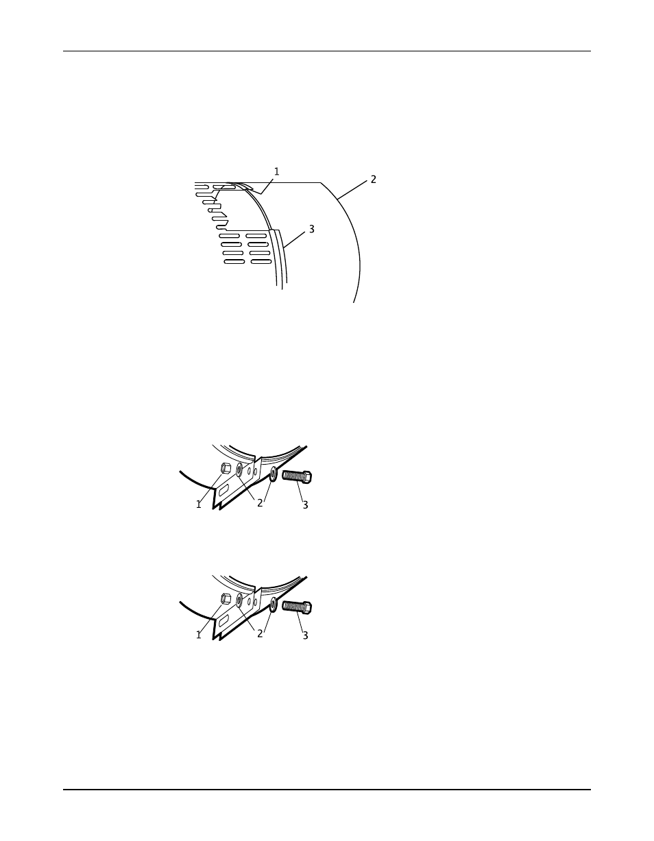
2. Slightly spread the opening of the coupling guard half and place it over the pump end plate.
The annular groove in the guard is located around the end plate.
Position the opening (flange) so that it does not interfere with the piping but still allows for
access when you install the bolts.
1. Annular groove
2. Deflector fan guard
3. Coupling guard half
3. Place one washer over the bolt and insert the bolt through the round hole at the front end of
the guard half.
4. Place a second washer over the exposed end of the bolt.
5. Thread a nut onto the exposed end of the bolt and tighten firmly.
This figure shows the proper sequence of components:
1. Nut
2. Washer
3. Bolt
1. Nut
2. Washer
3. Bolt
This figure shows an assembled unit:
36
Model 3600, API 610 8th, 9th, 10th & 11th Editions (ISO 13709) Installation, Operation, and Maintenance Manual