Goulds Pumps 3600 - IOM User Manual
Page 75
Maintenance
a) Clean the wear-ring seats thoroughly to make sure that they are smooth and free of
scratches.
b) Heat the new impeller wear rings to 180°F–200°F (82°C–93°C) using a uniform method
for heating, such as an oven, and place them on the impeller (101-101M) wear-ring
seats.
CAUTION:
Wear insulated gloves when you handle rings. Rings will be hot and can cause physical injury.
c) Tack weld each ring in place in three equidistant places.
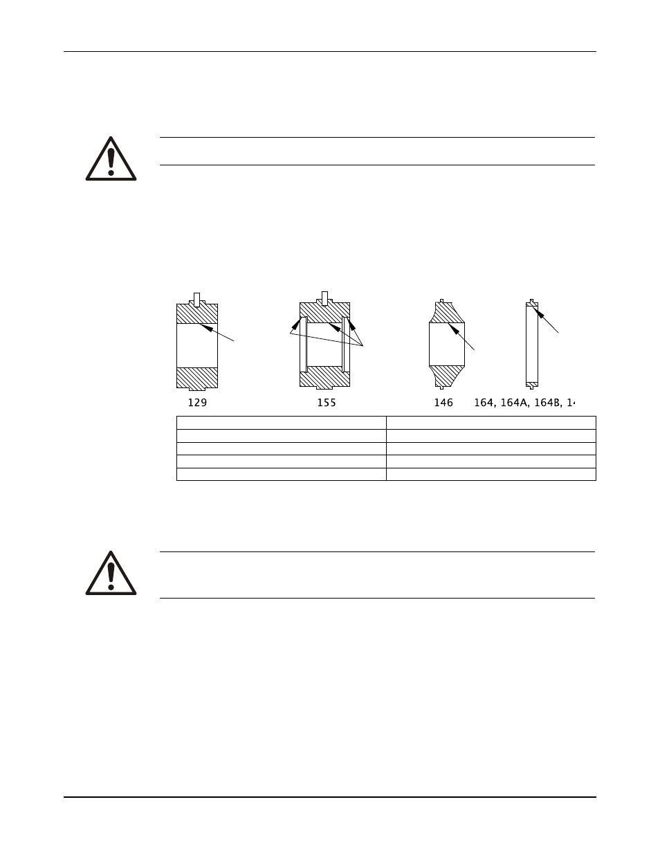
3. Check the throttle bushing (129), the center bushing (155), the diaphragm (146), the case
ring (164, 164A, 164B), and the stage ring (144) runout/distortion by measuring the bore at
three locations with inside micrometers or vernier calipers.
Correct any distortion in excess of 0.003 in. (0.076 mm) by machining prior to trimming new
impeller wear rings, if supplied.
The arrows point to wear surfaces on these parts.
Part number
Part name
129
Throttle bushing
155
Center bushing
146
Diaphragm
164, 164A, 164B, 144
Case and stage ring
4. Confirm the bore of the throttle bushing (129), the center bushing (155), the diaphragm
(146), the casing ring (164, 164A, 164B), and the stage ring (144).
5. Turn the impeller wear rings (202, 202A, 202B, 203) to size after mounting on the impeller
(101-101M).
CAUTION:
The impeller and wear-ring clearance setting procedures must be followed. Improperly setting the
clearance or not following any of the proper procedures can result in sparks, unexpected heat
generation, and equipment damage.
All replacement impeller wear rings are supplied 0.020 in. to 0.030 in. (0.508 mm to 0.762
mm) oversize. See Minimum running clearances for final running clearances. Machine the
impeller rings accordingly.
When the impeller assembly is supplied as a spare part (impeller with wear rings), the wear
rings are machined to the required dimension.
Model 3600, API 610 8th, 9th, 10th & 11th Editions (ISO 13709) Installation, Operation, and Maintenance Manual
73