Component parts, A335, Assembly & installation instructions – Hubbardton Forge 138815 User Manual
Page 5
Assembly & Installation Instructions
A335
Apparatus Pendant 138815
Page 5 of 5
Hand-Forged, Vermont-Made Lighting and Accessories
154 Route 30 South, Castleton, Vermont 05735
28309
To Complete Fixture Assembly
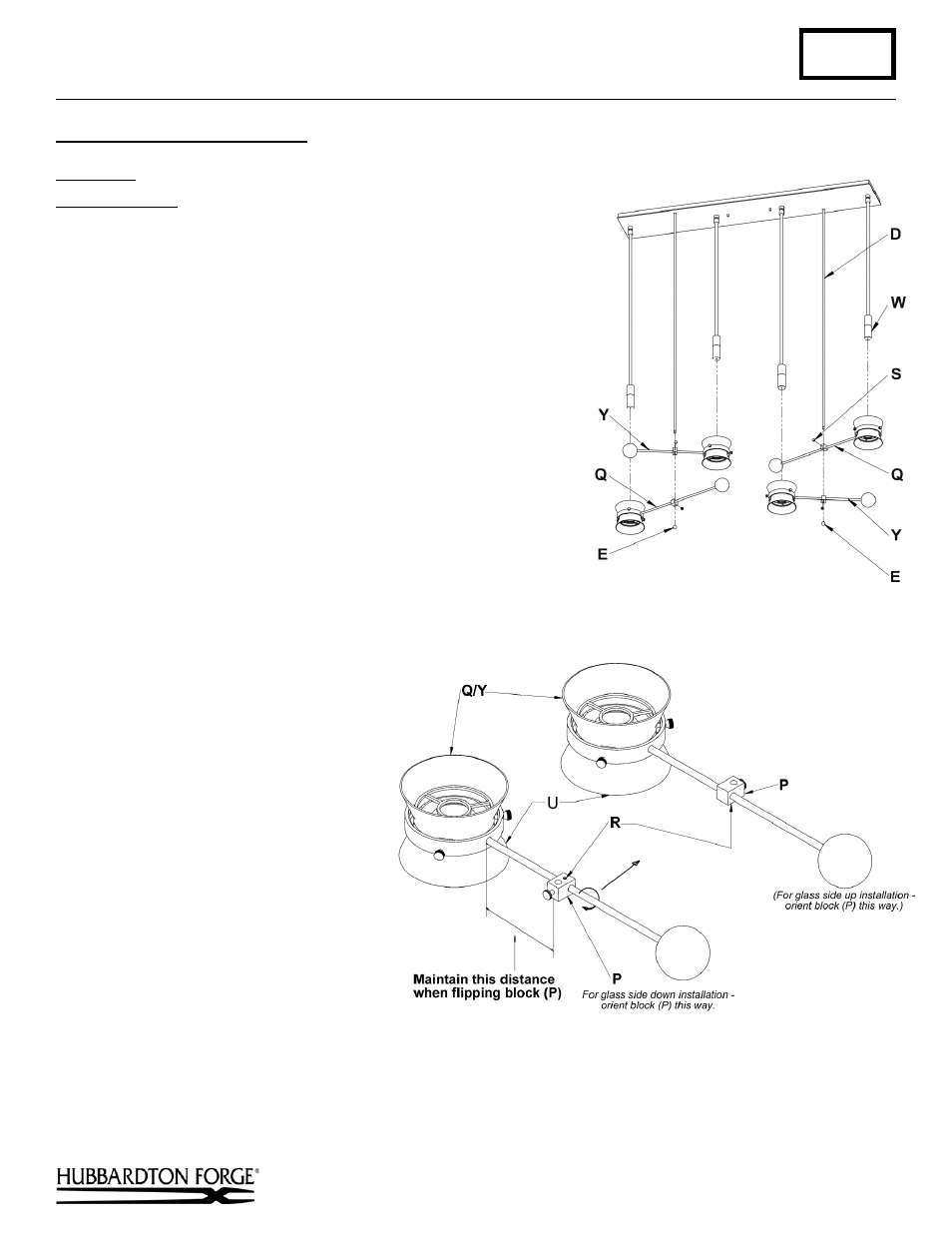
OPTION 2: GLASS SIDE UP (Figures 6 & 7)
Component Parts
D
¼” Diameter Rod
E
½” Diameter Ball
O
Counterweight
P
Block
Q
Short Fixture Body (2)
R
Set Screw
S
Thumb Screw
U
Glass
W
Shield
Y
Long Fixture Body (2)
1.
To install fixture with the glass side up, the orientation of the
block (P) must be changed (Figure 7). Set fixture body (Q/Y)
on a flat surface.
2.
Loosen set screw (R). Carefully flip block (P) over. Make
sure that the block stays the same distance from the
counterweight (O) and glass (U). Make sure that the top of the
block is parallel to the top of the fixture body (Q/Y)
(Figure 7). Retighten set screw (R).
3.
Remove balls (E) from rod (D) (Figure 6).
4.
Loosen thumb screw (S) from
block (P). Orient fixture body
(Q/Y) with glass side down. Slide
fixture body (Q/Y) up onto rod (D),
slipping the fixture body (Q/Y)
over the shield (W). Adjust to
desired height and tighten thumb
screw (S)
(Figure 6).
5.
Repeat step 2 for three other fixture
bodies (Q/Y) (Figure 6).
6.
Reattach balls (E) onto the
rods (D) (Figure 6).
7.
Restore electricity at main breaker.
If you need further assistance, or find that you are missing any parts, please contact the dealer from which you purchased
this product. We hope you enjoy your fixture!
* Hubbardton Forge will not be liable for injury or damage caused by improper installation, lamping or use of this fixture.
(Figure 6)
(Figure 7)