Component parts, A335, Assembly & installation instructions – Hubbardton Forge 138815 User Manual
Page 4
Assembly & Installation Instructions
A335
Apparatus Pendant 138815
Page 4 of 5
Hand-Forged, Vermont-Made Lighting and Accessories
154 Route 30 South, Castleton, Vermont 05735
28309
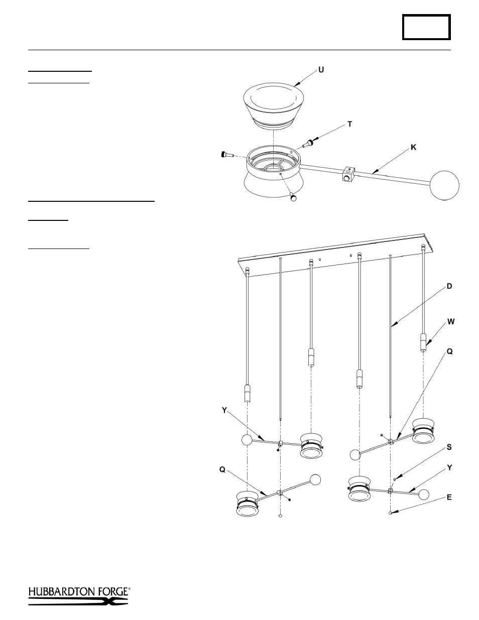
To Install Glass
(Figure 4)
Component Parts
U Glass
T Thumb Screw (3)
K Body
1.
Loosen the three thumb screws (T). It is not
necessary to remove them from the fixture.
2.
Lower glass (U) into fixture body (K) and
tighten thumb screws (T) equally, until snug
against glass.
To Complete Fixture Assembly
OPTION 1: GLASS SIDE DOWN (Figure 5)
(
For GLASS SIDE UP installation see next page)
Component Parts
D
¼” Diameter Rod (2)
E
½” Diameter Ball (2)
O
Counterweight
P
Block
Q
Short Fixture Body (2)
S
Thumb Screw
W
Shield
Y
Long Fixture Body (2)
1.
Remove balls (E) from rods (D).
Note: The fixture body (Q/Y) is factory
shipped ready installation with glass side
down. To reverse fixture and install with
glass side up, see To Complete Fixture
Assembly – GLASS SIDE UP (Figure 6)
next page.
2.
Loosen Thumb screw (S) from block (P).
Orient fixture body (Q/Y) with glass side
down. Slide fixture body (Q/Y) up onto
rod (D), slipping the fixture body (Q/Y)
over the shield (W). Adjust to desired
height and tighten thumb screw (S).
Note: Reference Figure 5 for installation
locations of Short fixture body (Q) and
long fixture body (Y).
3.
Repeat Step 2 for three other fixture
bodies (Q/Y).
4.
Reattach balls (E) onto the rods (D).
5.
Restore electricity at main breaker.
(continued)
(Figure 4)
(Figure 5)