Hubbardton Forge 207440 User Manual
B322, Assembly & installation instructions
H U B B A R D T O N F O R G E . C O M
hand-forged, vermont-made lighting and accessories
154 RT. 30 SOUTH
•
CASTLETON, VERMONT 05735
All designs and images ©1989-2013 Hubbardton Forge
®
. All rights reserved.
30900
Assembly & Installation Instructions
If you need further assistance, or find that you are missing any parts, please contact the dealer from which you purchased this product.
We hope you enjoy your fixture!
* Hubbardton Forge will not be liable for injury or damage caused by improper installation, lamping or use of this fixture.
Please Note: This fixture is designed to be mounted on a standard wall
surface and may not be suitable for all applications. If installing in a non-
wood frame application, we recommend consulting a qualified builder
or electrician.
Please Note: After installation, extra hardware and accessories may be
left due to kits being used on multiple products..
To Mount Fixture to Wall
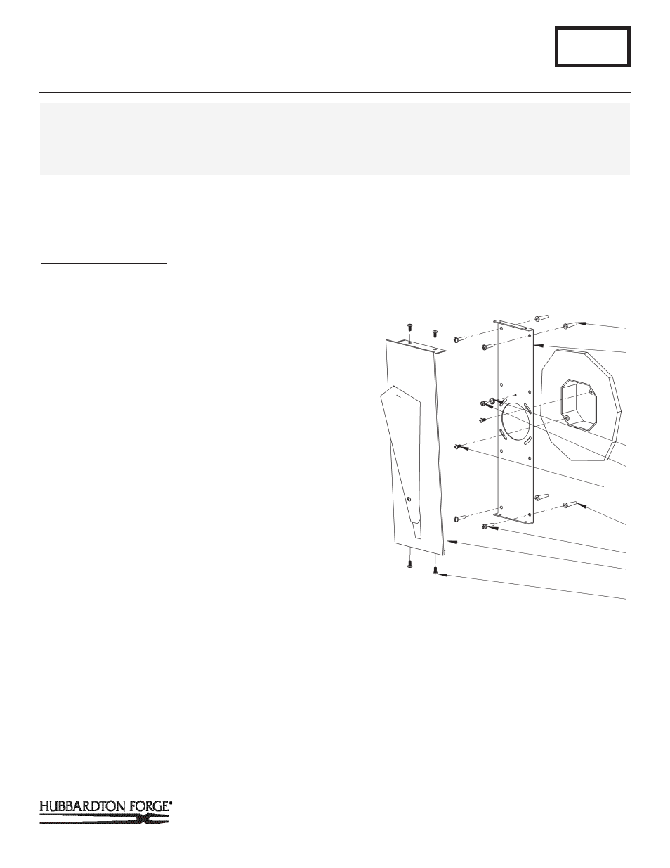
(Figure 1)
Component Parts
A Fixture
B Mounting Bracket
C Anchors (4)
D #10 Screws (4)
CAUTION: BE SURE POWER IS OFF AT THE MAIN BREAKER BOX
PRIOR TO INSTALLATION.
1. Carefully unpack the fixture from the carton.
2. Place the mounting bracket (B) over the electrical box being
sure to hold it plum and level. With a pencil, mark the loca-
tion of all mounting holes in the mounting bracket (B) on the
wall behind. Set mounting bracket aside.
3. Drill 1/4" holes in the locations marked on the wall. For holes
using anchors, place the tapered end of the anchors (C)
into the holes and gently tap them flush to the wall using a
light weight hammer.
4. Thread the wires in the electrical box through the hole in the
mounting bracket (B) while moving the bracket into position.
Using the 1" #10 screws (D), screw the bracket securely to
the wall. Be careful not to over-tighten or strip the anchors.
5. Using two machine screws (not provided) fasten the mount-
ing bracket (B) to the electric box.
Note: A new electric box comes with screws. When replacing an
existing fixture, retain screws for use with the new fixture.
6. Hold the fixture (A) close to the mounting bracket (B) and
using suitable wire connectors (not provided) connect fixture
wires to supply wires (white to white and black to black).
Attach cupped washer (E) and ground screw (F) to
mounting bracket and run a pigtail lead from the ground
screw (F) to the electrical box and connect all ground wires
(bare copper or green to bare copper or green).
B322
Quill Sconce 207440
Page 1 of 2
CAUTION: FAILURE TO INSTALL THIS FIXTURE PROPERLY MAY RESULT IN SERIOUS PERSONAL INJURY OR DEATH AND
PROPERTY DAMAGE. We recommend installation by a licensed electrician. This product must be installed in accordance with
applicable installation code(s), by a person familiar with the construction and operation of the product and the hazards involved.*
Caution: Do not exceed maximum wattage noted on fixture. Use only recommended bulbs with fixture.
(Figure 1)
(Continued)
E Cupped Washer
F Ground Screw
G #8 Black Screws (4)
C
E
B
F
D
G
A
C
MACHINE
SCREWS