Allied Telesis AT-CV5001 User Manual
Page 60
Chapter 2: Installation
60
3. With a 14-gauge wire-stripping tool, strip the three wires in the tray
cable coming from the DC input power source to 8mm
1mm (0.31 in.,
0.039 in.), as shown in Figure 28 on page 60.
Warning
Do not strip more than the recommended amount of wire. Stripping
more than the recommended amount can create a safety hazard by
leaving exposed wire on the terminal block after installation.
E10
Figure 28. Stripped Wire
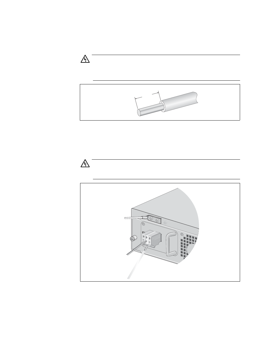
4. Insert the power supply ground wire into the middle connector of the
DC terminal and tighten the connection with a flathead screwdriver, as
shown in Figure 29.
Warning
When installing this equipment, always ensure that the power supply
ground connection is installed first and disconnected last.
E11
Figure 29. Inserting Wires into a DC Terminal Block
5. Connect the +48 VDC (RTN) feed wire to the terminal block marked
+ (plus).
8mm ±1mm
(0.31in. ±0.039in.)
A
FOR CENTRALIZED
RESTRICTED AREA.
INST
ALL ONL
Y IN A
CONNECTION,
DC PO
WER
AT-CV5001DC
DISCONNECT ALL PO
WER SOURCES &
REFER T
O MANU
AL BEFORE SER
VICING
40-60VDC
1640