Figure 17. inserting the at-cv5001dc power supply – Allied Telesis AT-CV5001 User Manual
Page 45
AT-CV5001 Media Converter Chassis Installation Guide
45
Note
Be sure to retain the slot cover and to reinstall it if you ever remove
the power supply from the unit. Open slots hamper the ability of the
cooling fan in the remaining power supply to maintain proper air
circulation in the chassis.
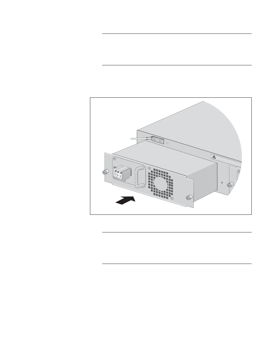
4. Orient the AT-CV5001DC Power Supply as shown in the figure and
gently slide the module into the slot until it is flush with the front of the
chassis.
Figure 17. Inserting the AT-CV5001DC Power Supply
Note
Light pressure may be needed to seat the module on the power and
control pins on the backplane inside the chassis. Do not force the
module. You might bend the pins. If there is resistance, remove the
module and try again.
5. Secure the AT-CV5001DC Power Supply to the chassis by tightening
the captive screws, as shown in Figure 15.
A
A
WARNING
This unit might h
ave more than one p
ower input.
To reduce the risk
of electric shoc
k, disconnect all po
wer inputs bef
ore ser
vicing unit.
o
AT-CV5001DC
FOR CENTRALIZED
RESTRICTED AREA.
INST
ALL ONL
Y IN A
CONNECTION,
DC PO
WER
DISCONNECT ALL PO
WER SOURCES &
REFER T
O MANU
AL BEFORE SER
VICING
40-60VDC
1657