Figure 14. inserting the at-cv5001ac power supply – Allied Telesis AT-CV5001 User Manual
Page 41
AT-CV5001 Media Converter Chassis Installation Guide
41
Note
Be sure to retain the slot cover and to reinstall it if you remove the
power supply from the unit. Open slots hamper the ability of the
cooling fan in the remaining power supply to maintain proper air
circulation in the chassis.
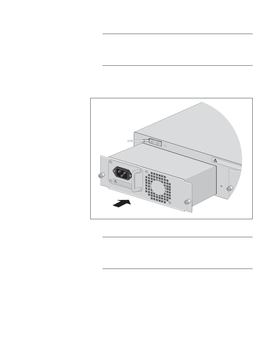
4. Orient the AT-CV5001AC Power Supply as shown in the figure and
gently slide the module into the slot until it is flush with the front of the
chassis.
Figure 14. Inserting the AT-CV5001AC Power Supply
Note
Light pressure may be needed to seat the module on the power and
control pins on the backplane inside the chassis. Do not force the
module. You might bend the pins. If there is resistance, remove the
module and try again.
A
WARNING
This u
nit m
ight h
ave m
ore th
an one
power in
put. To
reduce
the ris
k
of elec
tric s
hock, d
isconn
ect all p
ower in
puts b
efore s
ervicin
g unit
o
AT-CV5001
AC
DISCONNECT ALL P
OWER SUPPLIES &
REFER
TO MAN
UAL BEFORE SE
RVICING
.
100-240
VAC~
1656
- AT-GS908M (54 pages)
- AT-x230-10GP (80 pages)
- AT-GS950/48PS (64 pages)
- AT-GS950/10PS (386 pages)
- AT-GS950/16PS (386 pages)
- AT-GS950/48PS (386 pages)
- AT-9000 Series (258 pages)
- AT-9000 Series (1480 pages)
- IE200 Series (70 pages)
- AT-GS950/48 (378 pages)
- AT-GS950/48 (60 pages)
- AT-GS950/48 (410 pages)
- AT-GS950/8 (52 pages)
- SwitchBlade x8106 (322 pages)
- SwitchBlade x8112 (322 pages)
- SwitchBlade x8106 (240 pages)
- SwitchBlade x8112 (240 pages)
- AT-TQ Series (172 pages)
- AlliedWare Plus Operating System Version 5.4.4C (x310-26FT,x310-26FP,x310-50FT,x310-50FP) (2220 pages)
- FS970M Series (106 pages)
- 8100S Series (140 pages)
- 8100L Series (116 pages)
- x310 Series (116 pages)
- x310 Series (120 pages)
- AT-GS950/16 (44 pages)
- AT-GS950/24 (404 pages)
- AT-GS950/24 (366 pages)
- AT-GS950/16 (404 pages)
- AT-GS950/16 (364 pages)
- AT-GS950/8 (404 pages)
- AT-GS950/8 (364 pages)
- AT-GS950/8 (52 pages)
- AT-8100 Series (330 pages)
- AT-8100 Series (1962 pages)
- AT-FS970M Series (330 pages)
- AT-FS970M Series (1938 pages)
- SwitchBlade x3106 (288 pages)
- SwitchBlade x3112 (294 pages)
- SwitchBlade x3106 (260 pages)
- SwitchBlade x3112 (222 pages)
- AT-S95 CLI (AT-8000GS Series) (397 pages)
- AT-S94 CLI (AT-8000S Series) (402 pages)
- AT-IMC1000T/SFP (23 pages)
- AT-IMC1000TP/SFP (24 pages)
- AT-SBx3106WMB (44 pages)