Figure 13. removing the cover from slot b, Chapter 2: installation 40 – Allied Telesis AT-CV5001 User Manual
Page 40
Chapter 2: Installation
40
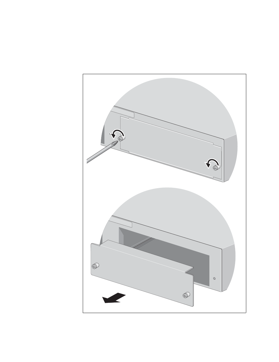
3. The power supply can be installed in either slot A or slot B. If this is the
initial installation and if you are installing just one power supply, Allied
Telesis recommends installing the module in slot A because that slot
does not have a cover. If you want to install the module in slot B,
remove the cover from the slot by loosening the two captive screws
with a cross-head screwdriver.
Figure 13. Removing the Cover from Slot B
WA
RNING
This unit might h
ave more than one p
ower input
. To reduce the risk
of electric sho
ck, disconnect all p
ower inputs be
fore se
rvicing unit
.
o
B
1681
WA
RNIN
G
This unit might h
ave more than one p
ower input
. To reduce the risk
of electric shoc
k, disconnect all po
wer inputs bef
ore ser
vicing unit.
o
B
1682
- AT-GS908M (54 pages)
- AT-x230-10GP (80 pages)
- AT-GS950/48PS (64 pages)
- AT-GS950/10PS (386 pages)
- AT-GS950/16PS (386 pages)
- AT-GS950/48PS (386 pages)
- AT-9000 Series (258 pages)
- AT-9000 Series (1480 pages)
- IE200 Series (70 pages)
- AT-GS950/48 (378 pages)
- AT-GS950/48 (60 pages)
- AT-GS950/48 (410 pages)
- AT-GS950/8 (52 pages)
- SwitchBlade x8106 (322 pages)
- SwitchBlade x8112 (322 pages)
- SwitchBlade x8106 (240 pages)
- SwitchBlade x8112 (240 pages)
- AT-TQ Series (172 pages)
- AlliedWare Plus Operating System Version 5.4.4C (x310-26FT,x310-26FP,x310-50FT,x310-50FP) (2220 pages)
- FS970M Series (106 pages)
- 8100S Series (140 pages)
- 8100L Series (116 pages)
- x310 Series (116 pages)
- x310 Series (120 pages)
- AT-GS950/16 (44 pages)
- AT-GS950/24 (404 pages)
- AT-GS950/24 (366 pages)
- AT-GS950/16 (404 pages)
- AT-GS950/16 (364 pages)
- AT-GS950/8 (404 pages)
- AT-GS950/8 (364 pages)
- AT-GS950/8 (52 pages)
- AT-8100 Series (330 pages)
- AT-8100 Series (1962 pages)
- AT-FS970M Series (330 pages)
- AT-FS970M Series (1938 pages)
- SwitchBlade x3106 (288 pages)
- SwitchBlade x3112 (294 pages)
- SwitchBlade x3106 (260 pages)
- SwitchBlade x3112 (222 pages)
- AT-S95 CLI (AT-8000GS Series) (397 pages)
- AT-S94 CLI (AT-8000S Series) (402 pages)
- AT-IMC1000T/SFP (23 pages)
- AT-IMC1000TP/SFP (24 pages)
- AT-SBx3106WMB (44 pages)