Front and rear panel components, Figure 2. front panel figure 3. rear panel, Line card slots led interface card – Allied Telesis AT-CV5001 User Manual
Page 17: Power supply slot a power supply slot b
AT-CV5001 Media Converter Chassis Installation Guide
17
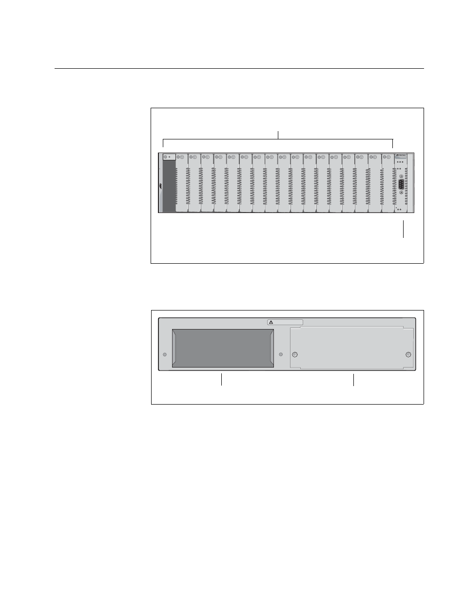
Front and Rear Panel Components
Figure 2 shows the front panel of the AT-CV5001 Chassis.
Figure 2. Front Panel
Figure 3 illustrates the rear panel of the chassis.
Figure 3. Rear Panel
FAN1
PS1
RDY
A
T
-CV5001
RDY FLT MASTER
RESET LINE/EXP
PS-A PS-B
FAN-A FAN-B
2
3
4
5
6
7
8
9
10
11
12
13
14
15
16
17
18
1649
1
Allied T
elesis
Line Card Slots
LED Interface
Card
1662
WARNING
This unit might have more than one power input. To reduce the risk
of electric shock, disconnect all power inputs before servicing unit.
o
A
B
Power Supply Slot A
Power Supply Slot B
See also other documents in the category Allied Telesis Computer hardware:
- AT-GS908M (54 pages)
- AT-x230-10GP (80 pages)
- AT-GS950/10PS (386 pages)
- AT-GS950/48PS (64 pages)
- AT-GS950/16PS (386 pages)
- AT-GS950/48PS (386 pages)
- AT-9000 Series (1480 pages)
- AT-9000 Series (258 pages)
- IE200 Series (70 pages)
- AT-GS950/48 (410 pages)
- AT-GS950/8 (52 pages)
- AT-GS950/48 (378 pages)
- AT-GS950/48 (60 pages)
- SwitchBlade x8112 (322 pages)
- SwitchBlade x8106 (322 pages)
- SwitchBlade x8106 (240 pages)
- SwitchBlade x8112 (240 pages)
- AT-TQ Series (172 pages)
- AlliedWare Plus Operating System Version 5.4.4C (x310-26FT,x310-26FP,x310-50FT,x310-50FP) (2220 pages)
- FS970M Series (106 pages)
- 8100L Series (116 pages)
- 8100S Series (140 pages)
- x310 Series (116 pages)
- x310 Series (120 pages)
- AT-GS950/24 (404 pages)
- AT-GS950/24 (366 pages)
- AT-GS950/16 (44 pages)
- AT-GS950/16 (364 pages)
- AT-GS950/16 (404 pages)
- AT-GS950/8 (404 pages)
- AT-GS950/8 (364 pages)
- AT-GS950/8 (52 pages)
- AT-8100 Series (330 pages)
- AT-8100 Series (1962 pages)
- AT-FS970M Series (330 pages)
- AT-FS970M Series (1938 pages)
- SwitchBlade x3106 (288 pages)
- SwitchBlade x3112 (294 pages)
- SwitchBlade x3106 (260 pages)
- SwitchBlade x3112 (222 pages)
- AT-S95 CLI (AT-8000GS Series) (397 pages)
- AT-S94 CLI (AT-8000S Series) (402 pages)
- AT-IMC1000T/SFP (23 pages)
- AT-IMC1000TP/SFP (24 pages)
- AT-SBx3106WMB (44 pages)