Warning – Alliance Laundry Systems D677I User Manual
Page 31
Installation
29
510969
© Copyright, Alliance Laundry Systems LLC – DO NOT COPY or TRANSMIT
Four-Wire Power Cord
IMPORTANT: Use only a U.L. listed No. 10 A.W.G.
(copper wire only) four conductor power supply
cord kit rated 240 Volts (minimum)
30 Amperes and labeled as suitable for use in a
clothes dryer.
NOTE: The power cord is not supplied with the
dryer when the dryer is shipped from the factory,
therefore, disregard steps 2 and 3 below when
connecting a four-wire power cord to a new dryer.
If the dryer has a three-wire cord attached, then
complete steps 1 through 12.
1. Remove the screw holding the access plate to the
rear of the dryer cabinet.
2. Remove the three screws holding the three wires
to the terminal block terminals. Save these
screws.
3. Loosen the strain relief screw and pull the cord or
wires out through the rear of the dryer.
4. Remove the terminal bracket ground screw
holding the ground wire to the terminal block
mounting bracket. Save the screw.
NOTE: ON NEW DRYERS, this is the ground wire
that goes from the neutral (center) terminal on the
terminal block to the mounting bracket.
Install four-wire power cord
5. Route the end of the four-wire power cord
through the strain relief. DO NOT tighten the
strain relief screws at this time.
6. Insert the end of power cord and strain relief
through the hole in the rear of the dryer cabinet.
Install the strain relief nut from the inside of the
cabinet and tighten firmly.
7. Attach the green ground wire (from the four-wire
power cord) to the terminal block mounting
bracket using the hex head screw removed in
step 4. Tighten the screw firmly.
8. Using the three wire-binding (10-32 x 3/8")
screws from the accessories envelope located
inside the cylinder (unless the screws were
previously removed in step 2), attach the power
cord wires to the terminal block terminals as
follows:
a. Red to Red
b. Black to Black
c. White to White (refer to NOTE below)
NOTE: When installing the white wire, loop the
free eyelet end of the ground wire (from step 4) and
place it together with the white wire and attach
both wires to the neutral (center) terminal on the
terminal block. Refer to Figure 21.
IMPORTANT: Failure to tighten the nuts firmly on
the terminal block may result in power cord wire
failure.
9. Tighten the two strain relief screws to secure the
power cord.
10. Recheck all screws to be sure they are tight.
11. Check the continuity of the ground connection
before plugging the cord into an outlet. Use an
acceptable indicating device connected to the
center grounding pin of the plug and the green
screw on the back of the cabinet. Refer to
Figure 18.
12. Reinstall the access plate and screw to the rear of
the dryer cabinet.
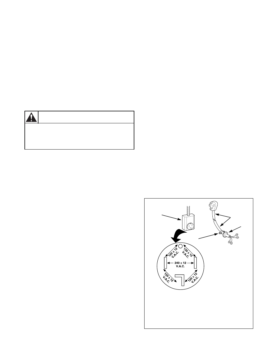
Figure 20
To reduce the risk of electrical shock,
disconnect the electrical power to the dryer
before proceeding.
W137
WARNING
D815I
1
Typical Four-Wire Receptacle
2
Power Cord – Not supplied with dryer
(Four-Wire)
3
Strain Relief Nut
4
Strain Relief
1
4
2
3