34933a d-sub connectors for two-wire mode, Matrix 1 matrix 2, Matrix switch modules – Agilent Technologies Switch/Measure User Manual
Page 168: Description pin
156
34980A User’s Guide
5
Matrix Switch Modules
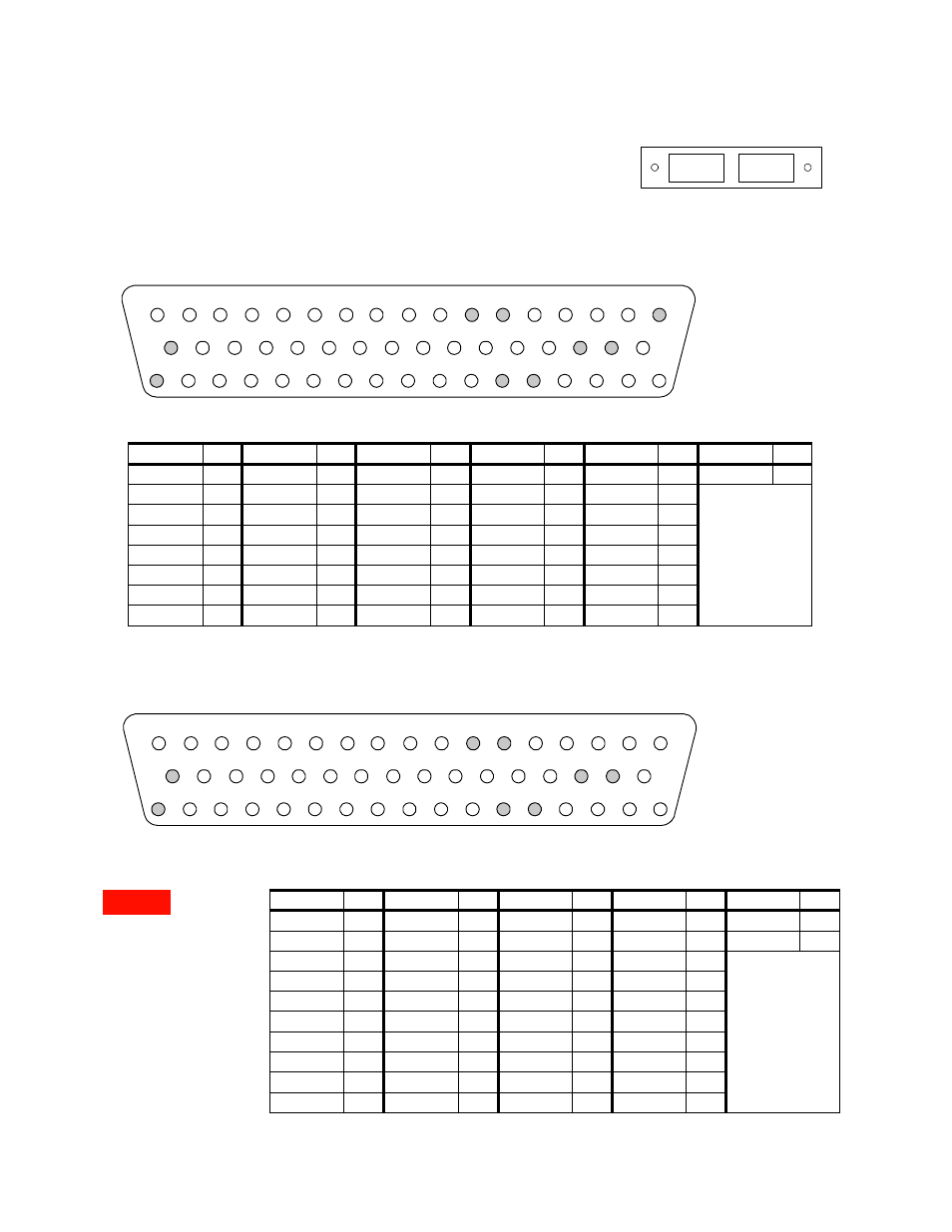
34933A D-Sub Connectors for Two-Wire Mode
Matrix 1
Matrix 2
For orientation, the D-sub connector
end of the module is facing you.
Matrix 1
Matrix 2
NOTE:
•
In this diagram and the
table below, R
represents “row,” and C
represents “column.”
•
Bypass” means to bypass
the 100
Ω in-rush resistor
that protects the reed
relays.
1
2
3
4
5
6
7
8
9
10
11
12
13
14
15
16
17
18
19
20
21
22
23
24
25
26
27
28
29
30
31
32
33
34
35
36
37
38
39
40
41
42
43
44
45
46
47
48
49
50
NC
C4H
C4L
R4H
R4L
C5H
C5L
NC
NC
C7H
C7L
C4H
bypass
C4L
bypass
C5H
bypass
C5L
bypass
C7H
bypass
C7L
bypass
C2L
NC
C2H
R2H
R2L
C8H
C8L
NC
NC
GND
C3H
bypass
C1L
bypass
C1H
bypass
C3L
bypass
C6L
bypass
C6H
bypass
C6L
NC
C3H
C3L
C1H
C1L
R3H
R3L
C6H
NC
R1H
R1L
NC
C2H
bypass
C2L
bypass
C8H
bypass
C8L
bypass
Description Pin
Description Pin
Description Pin
Description Pin
Description Pin
Description Pin
R1H
49
C1H
37
C5H
7
C1H bypass 21
C5H bypass 9
GND
33
R1L
50
C1L
38
C5L
8
C1L bypass
22
C5L bypass
10
No Connect pins:
11-12, 17-18, 31-32,
34, and 45-46
R2H
27
C2H
23
C6H
41
C2H bypass 43
C6H bypass 25
R2L
28
C2L
24
C6L
42
C2L bypass
44
C6L bypass
26
R3H
39
C3H
35
C7H
13
C3H bypass 19
C7H bypass 15
R3L
40
C3L
36
C7L
14
C3L bypass
20
C7L bypass
16
R4H
5
C4H
1
C8H
29
C4H bypass 3
C8H bypass 47
R4L
6
C4L
2
C8L
30
C4L bypass
4
C8L bypass
48
NOTE:
•
In this diagram and the
table below, R
represents “row,” and C
represents “column.”
•
“Bypass” means to
bypass the 100
Ω in-rush
resistor that protects the
reed relays.
18
19
20
21
22
23
24
25
26
27
28
29
30
31
32
33
C2L
NC
C2H
R6H
R6L
C8H
C8L
NC
NC
Interlock
C3H
bypass
C1L
bypass
C1H
bypass
C3L
bypass
C6L
bypass
C6H
bypass
1
2
3
4
5
6
7
8
9
10
11
12
13
14
15
16
17
Interlock
C4H
C4L
R8H
R8L
C5H
C5L
NC
NC
C7H
C7L
C4H
bypass
C4L
bypass
C5H
bypass
C5L
bypass
C7H
bypass
C7L
bypass
34
35
36
37
38
39
40
41
42
43
44
45
46
47
48
49
50
C6L
NC
C3H
C3L
C1H
C1L
R7H
R7L
C6H
NC
R5H
R5L
NC
C2H
bypass
C2L
bypass
C8H
bypass
C8L
bypass
Description Pin
Description Pin
Description Pin
Description Pin
Description Pin
R5H
49
C2H
23
C7H
13
C4H bypass 3
Interlock
17
R5L
50
C2L
24
C7L
14
C4L bypass 4
Interlock
33
R6H
27
C3H
35
C8H
29
C5H bypass 9
No Connect pins:
11-12, 18, 31-32, 34,
and 45-46
R6L
28
C3L
36
C8L
30
C5L bypass 10
R7H
39
C4H
1
C1H bypass 21
C6H bypass 25
R7L
40
C4L
2
C1L bypass 22
C6L bypass 26
R8H
5
C5H
7
C2H bypass 43
C7H bypass 15
R8L
6
C5L
8
C2L bypass 44
C7L bypass 16
C1H
37
C6H
41
C3H bypass 19
C8H bypass 47
C1L
38
C6L
42
C3L bypass 20
C8L bypass 48
WARNING::
As a safety
feature, interlock pins (17
and 33) must be shorted to
enable the Analog Bus
relays, which are on Matrix
2, to close. The optional
34933T-001 (for 2-wire)
terminal block shorts these
pins for you. This feature
protects inadvertent routing
of high voltages from the
Analog Bus to the D-sub
connector of the module.
WARNING