34931a simplified schematic, Matrix switch modules, Matrix 1 matrix 2 – Agilent Technologies Switch/Measure User Manual
Page 157: Analog buses
Matrix Switch Modules
5
34980A User’s Guide
145
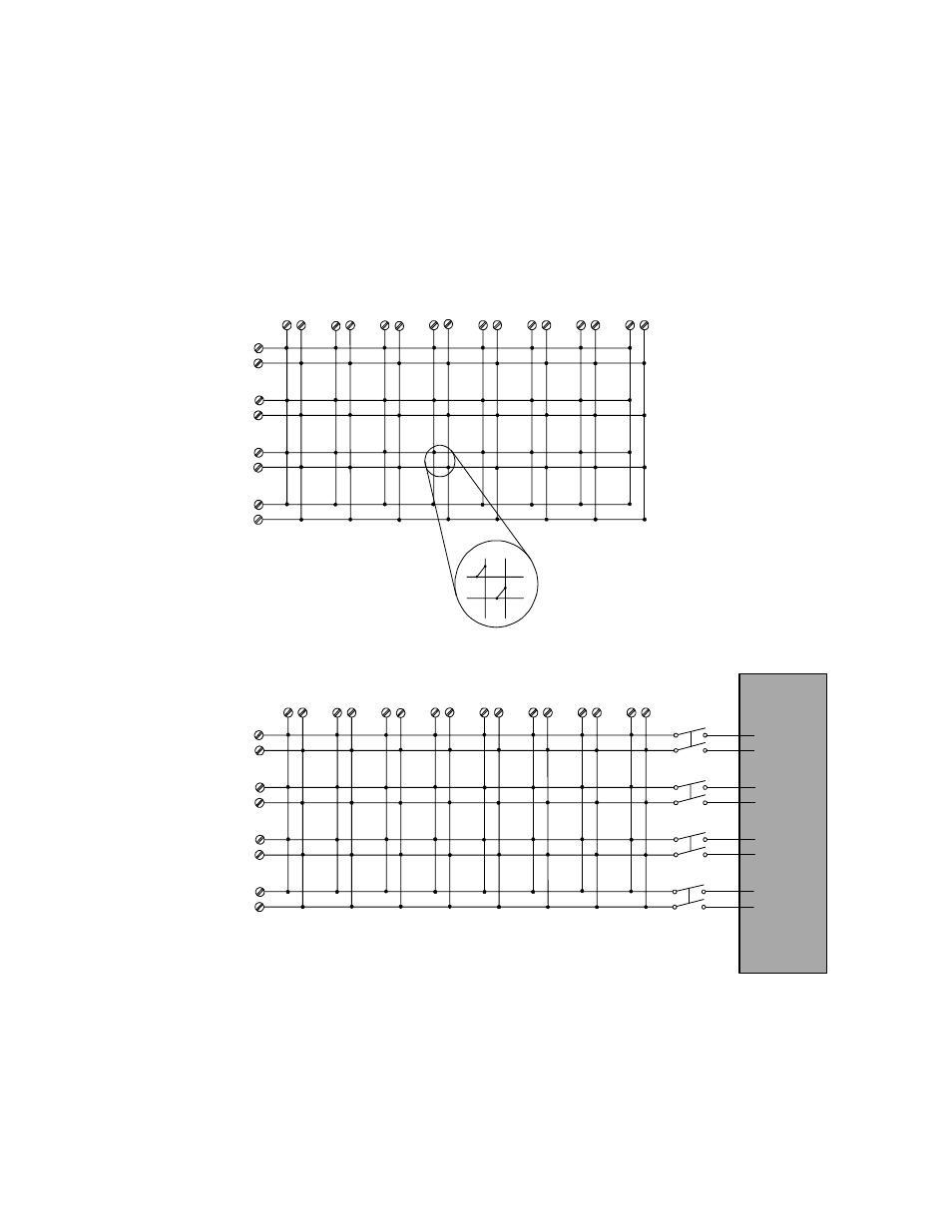
34931A Simplified Schematic
H
H
L
L
H
H
H
H
H
H
H
H
L
L
L
L
L
L
L
L
L
L
L
L
H
H
H
ABus1
DMM
(MEAS)
ABus2
DMM
(SENS)
ABus3
ABus4
922
923
924
921
H
L
H
L
H
L
H
L
H
L
H
L
H
L
H
L
L
L
L
L
H
H
H
H
H
H
H
L
L
L
L
Matrix 1
Matrix 2
NOTE: Three-digit channel numbers are
derived from the intersection of the rows and
columns, columns having two digits. The
intersection shown here represents Channel
304 (Row 3, Column 4)
Row 1
Row 2
Row 3
Row 4
Col 1
Col 2
Col 3
Col 4
Col. 6
Col 7
Col 8
Col 5
Col 1
Col 2
Col 3
Col 4
Col 6
Col 7
Col 8
Col 5
Analog Buses
NOTE: Although columns are numbered the
same on the two matrices, they are electrically
separate.
NOTE:
Matrix relays: Armature latching
Analog Bus relays: Armature non-latching
Row 1
Row 2
Row 3
Row 4
Row 1
Row 2
Row 3
Row 4