Horner APG SmartStix Analog Programming Guide User Manual
Page 8
PAGE 8
24 SEP 2003
MAN0703-01
The standard digital filter is useful for applications with significant amounts of random (Gaussian) noise.
The slower time constants, while yielding better noise suppression, take a longer time to settle after step
changes and are also somewhat sensitive to impulse noise which is treated like Gaussian noise and
averaged in.
Bit 16 may be set to specify an adaptive filter algorithm that:
1. Responds much more quickly to large step changes at slower time constants with full filtering
of low level noise.
2. Suppresses impulse noise at the expense of slightly slower response at the shortest time
constant settings. (Approximately 10 additional milliseconds)
Note that actual system response time is network dependent.
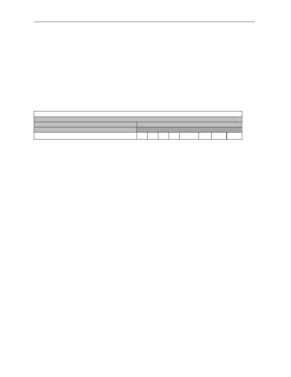
Table 8 – Consumed Directed Digital Data Word 3
16-bit Word
8-bit High Byte
8-bit Low Byte
Diagnostic Command Data
Configuration Command Data
Reserved for Future Products
CAIT
CIT
CHT
CLT
CLT = 0
Command the SmartStix I/O Module to set its Life Expectancy Time to 2.0 seconds, as the maximum
time to wait between Control Station to SmartStix I/O Module output control data messages, before
s etting all Digital Outputs to their default states.
CLT = 1
Command the SmartStix I/O Module to use Word 4’s Life Expectancy Time. In this case, a value of 0.0
disables the Life Expectancy feature.
CHT = 0
Command the SmartStix I/O Module to set its Heartbeat Send Time to 1.0 second, as the minimum time
between SmartStix I/O Module to Control Station Heartbeat messages.
CHT = 1
Command the SmartStix I/O Module to use Word 4’s Heartbeat Send Time. In this case, a value of 0.0
disables the Heartbeat Send feature.
CIT = 0
For digital modules, command the SmartStix I/O Module to send its Digital Input data to the Control
Station, only when the Digital Inputs change state.
CIT = 1
For digital modules, command the SmartStix I/O Module to use Word 4’s Input Send Time, to determine
how often to periodically send its Digital Input data to the Control Station. In this case, a value of 0.0
disables automatic sending of Digital Input data.
CAIT = 0
For analog modules, command the SmartStix I/O Module to send its Analog Input data to the Control
Station every 500 milliseconds.
CAIT = 1
For analog modules, command the SmartStix I/O Module to use Word 4’s Input Send Time, to
determine how often to periodically send its Digital Input data to the Control Station. In this case, a
value of 0.0 disables automatic sending of Digital Input data.
Note:
Regardless of the CIT / CAIT setting, Inputs are always sent to the Control Station when the
SmartStix I/O Module powers -up, and when specifically requested by the Control Station.