Horner APG SmartStix Analog Programming Guide User Manual
Page 7
MAN0703-01
24 SEP 2003
PAGE 7
M16..M1
Mode bits. A low mode bit selects ±10V and a high mode bit selects ±20mA.
F15..F13
Filter bits. Input digital filter time constant codes for analog input modules.
A16
Adaptive filter enable bit for analog input modules.
F13 through F15 and A16 are used in place of M13 through M16 by modules with analog
inputs.
S16..S1
Scale bits. A low scale bit selects ±10V or ±20mA for the corresponding channel. A
high scale bit selects ±5V or 4-20mA. S13 through S16 are not used by modules with
analog inputs.
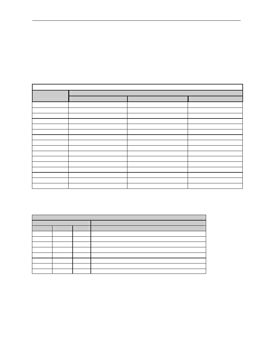
Table 6 - Mode & Scale Bit to Channel Correspondence
Channel
Bit
HE550ADC970
HE550MIX977
HE550DAC207
M1, S1
INPUT CHANNEL 1
INPUT CHANNEL 1
Not used
M2, S2
INPUT CHANNEL 2
INPUT CHANNEL 2
Not used
M3, S3
INPUT CHANNEL 3
INPUT CHANNEL 3
Not used
M4, S4
INPUT CHANNEL 4
INPUT CHANNEL 4
Not used
M5, S5
INPUT CHANNEL 5
INPUT CHANNEL 5
Not used
M6, S6
INPUT CHANNEL 6
INPUT CHANNEL 6
Not used
M7, S7
INPUT CHANNEL 7
INPUT CHANNEL 7
Not used
M8, S8
INPUT CHANNEL 8
INPUT CHANNEL 8
Not used
M9, S9
INPUT CHANNEL 9
OUTPUT CHANNEL 1
OUTPUT CHANNEL 1
M10, S10
INPUT CHANNEL 10
OUTPUT CHANNEL 2
OUTPUT CHANNEL 2
M11, S11
INPUT CHANNEL 11
OUTPUT CHANNEL 3
OUTPUT CHANNEL 3
M12, S12
INPUT CHANNEL 12
OUTPUT CHANNEL 4
OUTPUT CHANNEL 4
F13, M13, S13
See filter bits.
See filter bits.
OUTPUT CHANNEL 5
F14, M14, S14
See filter bits.
See filter bits.
OUTPUT CHANNEL 6
F15, M15, S15
See filter bits.
See filter bits.
OUTPUT CHANNEL 7
A16, M16, S16
See filter bits.
See filter bits.
OUTPUT CHANNEL 8
Each analog input has a single pole 345Hz (461uS) cutoff high frequency noise filter. In addition a
second digital filter may be specified with the following time constants.
Table 7 - Time Contstants
Filter Bit
Time Constant
15
14
13
0
0
0
10 milliseconds (Nominal hardware scan rate)
0
0
1
15 milliseconds
0
1
0
35 milliseconds
0
1
1
75 milliseconds
1
0
0
155 milliseconds
1
0
1
315 milliseconds
1
1
0
635 milliseconds
1
1
1
1.275 seconds