Horner APG SmartStix Analog Programming Guide User Manual
Page 2
PAGE 2
24 SEP 2003
MAN0703-01
2
BASIC SMARTSTIX PROGRAMMING
2.1
Using GET and PUT
2.1.1
Get Remote I/O Function Block
This function handles receiving data from a remote I/O device and places the received data in a set of
registers specified by the user. This function passes power flow if the function is actively receiving data /
heartbeat messages from the remote I/O device. This function stops passing power flow if it has not
received data / heartbeat messages from the remote I/O device for 2000 milliseconds.
A remote I/O device consists of a CsCAN device such as a SmartStix Module that transmits global data
and receives directed network data.
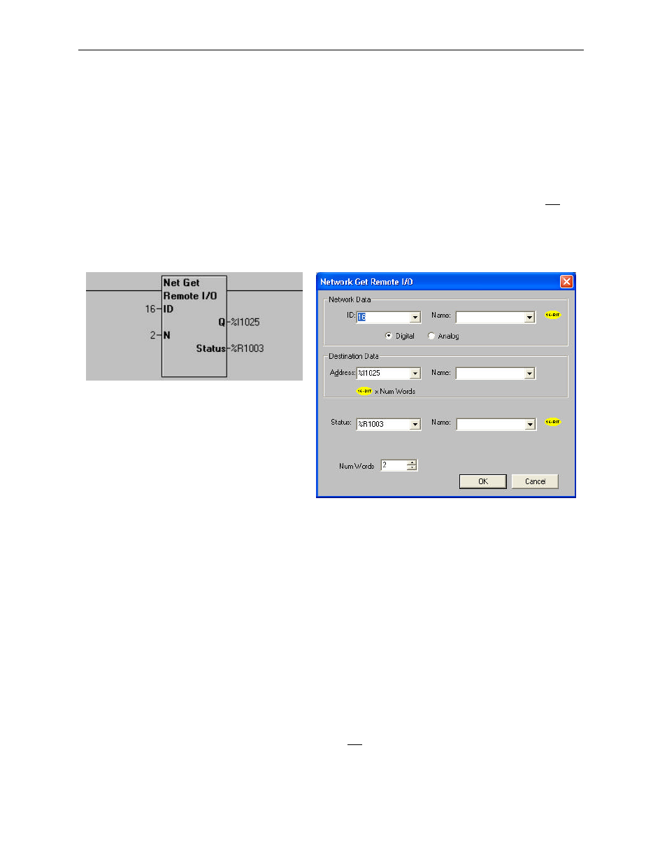
Figure 1 – Get Remote I/O Function Block and Parameter Screen
2.1.2
Get Remote Parameter Description:
ID – This is the network ID of the remote I/O from which to receive data. This can be a constant from 1 to
253 or a 16-bit register.
Digital / Analog – These radio buttons allow choosing digital or analog network data. Remote I/O
devices with discrete inputs/outputs normally require digital data. Remote I/O devices such as voltage,
current or thermocouple would require analog data.
Destination Data Address – This is the location to start placing data received from the remote I/O
device. The number of registers used is defined by the Num Words parameter in this section. Any valid
read/write OCS reference types can be used (%R, %AI, %I, %M, etc.).
Status – This 16-bit register is used internally. It must not written by any other function block. Use the
power flow from this function for the pass/fail status.