3advanced smartstix programming – Horner APG SmartStix Analog Programming Guide User Manual
Page 6
PAGE 6
24 SEP 2003
MAN0703-01
3
ADVANCED SMARTSTIX PROGRAMMING
3.1
SmartStix I/O Module Device Classes
There are currently three SmartStix Analog I/O Module device classes (8, 9, and 10) that control and
monitor Analog I/O points and exchange Directed and Global Analog Data words with a Control Station
via the CsCAN Network.
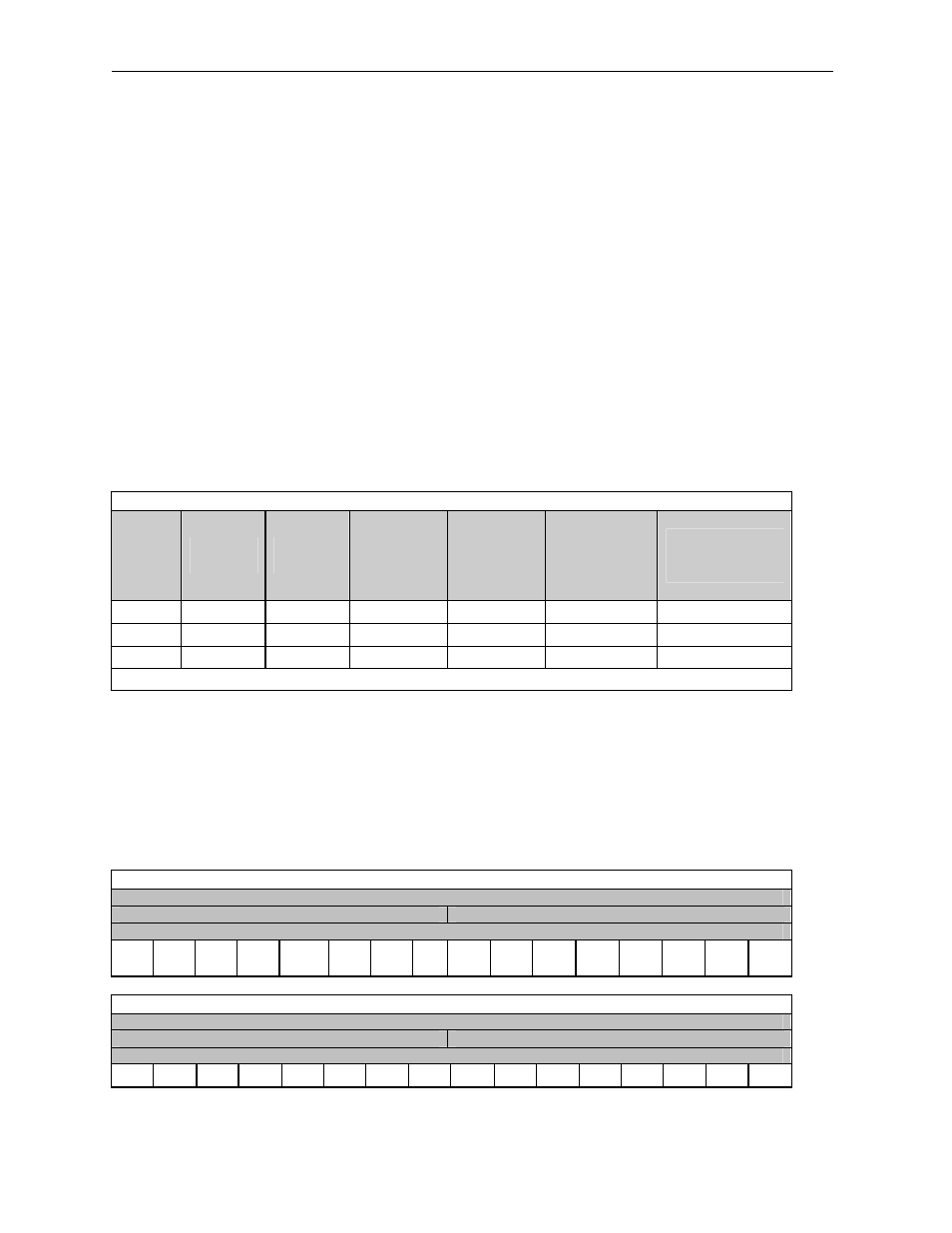
Table 3 shows the three device classes along with the number of I/O points they contain and the number
of Directed and Global Data words they exchange. Note that the digital outputs are virtual and do not
correspond to physical outputs. They are used by the Analog module firmware to configure the individual
analog channels.
Example: Determining the class of a SmartStix module:
1. Identify the row containing the corresponding quantity of analog I/O in Table 3.
2. The device class is located in the same row along with the total number of words consumed
and produced for that device class.
Table 3 – SmartStix I/O Module Device Classes
Device
Class
Analog
Inputs
Analog
Outputs
Directed
Digital
Data
Words
Consumed
Global
Digital
Data
Words
Produced
Directed
Analog Data
Words
Consumed
Global Analog
Data Words
Produced
8
12
0
4
4
0
12
9
8
4
5
4
8
8
10
0
8
5
4
16
0
Device classes greater than 10 are reserved for future products.
The following terms are defined:
Consumed Data:
Directed Data received by a SmartStix I/O Module from a Control Station
Produced Data:
Global Data transmitted by a SmartStix I/O Module to a Control Station
Table 1 summarizes SmartStix I/O module consumed and produced data words. For advanced users,
the following sections describe the consumed and produced words in detail.
3.2
SmartStix I/O Module Consumed (Received) Directed Data
Table 4 – Consumed Directed Digital Data Word 1
16-bit Word
8-bit High Byte
8-bit Low Byte
Digital Output Control Data – Low Word
A16
M16
F15
M15
F14
M15
F13
M15
M12
M11
M10
M9
M8
M7
M6
M5
M4
M3
M2
M1
Table.5 – Consumed Directed Digital Data Word 2
16-bit Word
8-bit High Byte
8-bit Low Byte
Digital Output Control Data - High Word
S16
S15
S14
S13
S12
S11
S10
S9
S8
S7
S6
S5
S4
S3
S2
S1