Horner APG SmartStix Analog Programming Guide User Manual
Page 11
MAN0703-01
24 SEP 2003
PAGE 11
4
SmartStix I/O Module LED Indicators
SmartStix I/O Modules provide diagnostic and status LED indicators
4.1
Diagnostic LED Indicators
The MS an NS diagnostic LEDs indicate the fault status of the module and the network, respectively.
Note that the diagnostic LEDs correspond directly to the Module Fault and Network Fault bits as shown in
Table
.
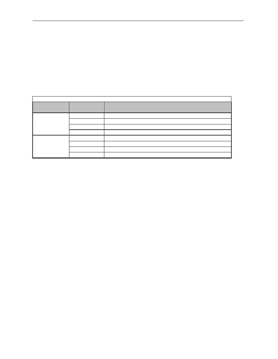
The following table shows the possible LED states and their meanings:
Table 16 – SmartStix I/O Module Diagnostic LED Indicators
Diagnostic
LED
State
Meaning
Solid Red
RAM or ROM test failed (RAM or ROM bit On)
Blinking Red
I/O test failed (I/O bit On)
Blinking Green
Module is in power-up state (PUP bit On)
MS
(Module
Status)
Solid Green
Module is running normally (all Module Fault bits Off)
Solid Red
Network Ack or Dup ID test failed (NAK or DUP bit On)
Blinking Red
Network ID test failed (ID bit On)
Blinking Green
Module is in Life Expectancy default state (LIFE bit On)
NS
(Network
Status)
Solid Green
Network is running normally (all Network Fault bits Off)
4.2
Status LED Indicators
In addition to the MS and NS diagnostic LED indicators described above, SmartStix I/O Modules also
provide a Power Status LED, which illuminates Red when power is applied to the module.
Also, there are I/O Status LED indicators for each of the Digital I/O points, which illuminate Red when the
I/O point is On.
5
SmartStix I/O Module Network ID
Each SmartStix I/O Module (as well as all other CsCAN Nodes on the CsCAN Network) must be assigned
a unique Network ID number, to arbitrate network data exchanges.
Since a Network ID is a number in the range 1 to 253, up to 253 CsCAN Nodes can be logically
connected to a CsCAN Network. However, the use of standard CAN transceiver chips, limits the number
of physically attached devices to 64. Thus, to reach the logical limit of 253 devices, up to three smart
CAN repeaters (HE200CGM100) are used, to connect groups of devices together.
Assigning a SmartStix I/O Module’s Network ID is accomplished by setting its two hexadecimal (base 16)
Network ID rotary switches, which are labeled HI and LO. Each rotary switch has 16 positions, labeled 0,
1, 2, 3, 4, 5, 6, 7, 8, 9, A, B, C, D, E and F, where A through F represent the decimal values 10 through
15. The Network ID rotary switches are set as follows:
Network ID
= (Network ID
HI
x 16) + Network ID
LO
This allows the Network ID to be set to any number from 0 to 255. However, since Network IDs 0, 254
and 255 (00, FE and FF) are reserved for other purposes, they are illegal settings for a SmartStix I/O
Module. If a SmartStix I/O Module’s rotary switches are set for an illegal Network ID, a default Network ID
of 253 will be used, the ID Network Fault bit will be On, and the NS LED will blink Red.