13 connection with the current loop line, 14 connection with the rs232 line, 15 adjusting the voltage of the optics controls – Videotec EXDTRX User Manual
Page 17
EN - English - I
nstruc
tions manual
15
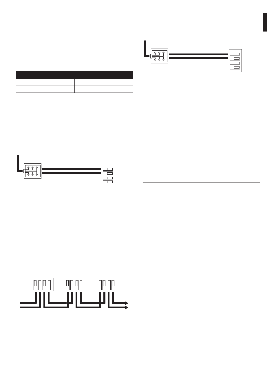
6.2.14 Connection with the RS232 line
GND
RX
RS232
Al connettore
RJ11 della
tastiera
TX RS232 (Nero)
GND RS232 (Verde)
Morsetti sul
ricevitore
Fig. 17
Communication mode RS232, max distance 15m.
6.2.15 Adjusting the voltage of the
optics controls
• Connect the power supply cable and power the
unit (LD1 lit up);
• Insert a load between terminals FOCUS NEAR and
FOCUS FAR to absorb at least 10 mA (use a resistor
from 100 to 1000 ohm);
• Position the tester prods on terminals FOCUS NEAR
and FOCUS FAR;
• Keep one of the two FOCUS keys on the control
unit pressed down;
• Adjust the control voltage of the optics by
adjusting trimmer TR1 ( default 12Vdc).
h
Don’t make unloaded voltage regulation
(without inserting the load) otherwise the
adjustment will be incorrect.
6.2.13 Connection with the Current
Loop line
The various devices can be connected directly using
the telephone cable supplied by the manufacturer.
For normal connections in the field, refer to the
connections made using the shunt boxes RJ, supplied
by the manufacturer, following the reference tables
given below:
KEyBOARD
EXDTRX3, EXDTRX324
TX CL Yellow
Terminal RX CL
GND CL Red
Terminal AGND
Tab. 02 Current Loop Communication Mode, max. distance
1500 meters from receiver, Jumper JP2 and JP3 in
position CL.
From the receiver side the connection should be
made to terminals RXCL and AGND according to the
following scheme:
AGND
TX
AGND
RX
CURRENT LOOP
To RJ11
keyboard
connector
TX CL (Yellow)
GND CL (Red)
Receiver
clamps
Fig. 15
• If the receiver is connected in cascade to another
EXDTRX3 / EXDTRX324 unit, the reception mode
should be set in Current Loop with jumpers JP2
and JP3 in position CL.
• Terminals RX CL and AGND should be connected
to the preceding unit terminals TX CL and AGND
respectively as in the following scheme:
Current
Loop
A
GND
TX
A
GND
RX
Current
Loop
A
GND
TX
A
GND
RX
Current
Loop
A
GND
TX
A
GND
RX
From previous
receiver
To next
receiver
Fig. 16