Videotec EXDTRX User Manual
Page 16
EN - English - I
nstruc
tions manual
14
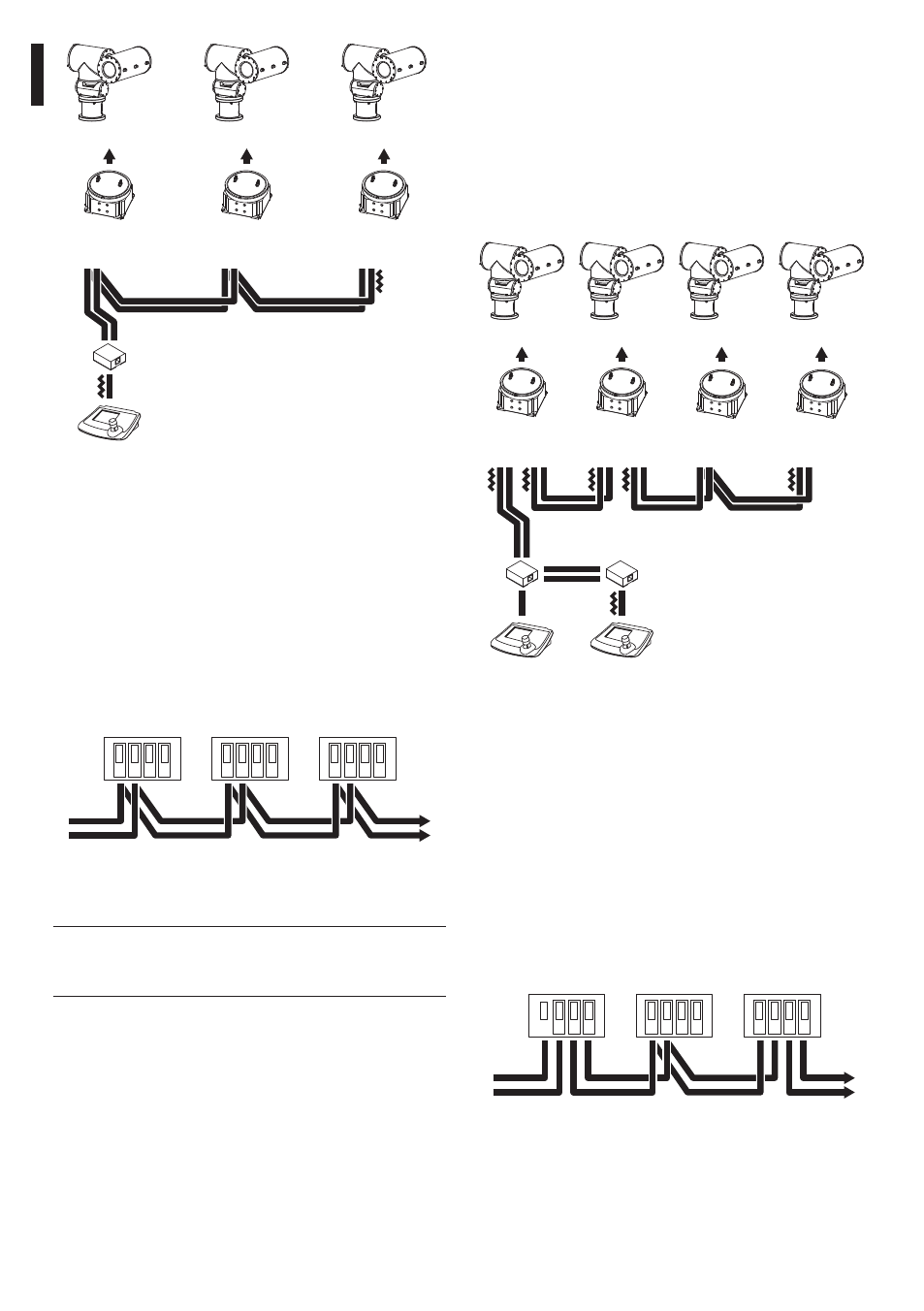
6.2.12 Mixed configurations (point-to-
point / multi-point)
This is a combination of the two previous connection
modes and, depending on the combination chosen,
allows the user to exploit the advantages of the
two types of connection to the utmost, significantly
reducing the probability of faulty operation.
The following is an example of mixed connection:
R2
R1
K2
EXPT
EXPT
EXDTRX3
EXDTRX324
EXDTRX3
EXDTRX324
R3
R4
EXPT
EXPT
EXDTRX3
EXDTRX324
EXDTRX3
EXDTRX324
L4
L3
L2
L1
L1
K1
DCT
DCT
Fig. 13
In the example shown, if receiver R3 jams (multi-
point connection in line L3) it will not cause faulty
operation in receiver R4.
R3 is not at the ends of line L3and
it is not therefore necessary to terminate it.
If receiver R2 jams, since it is the "generator" of line
L3, all receivers connected to it in cascade (R3 and R4)
will not receive the commands.
RS485
TX-
B
TX-
A
RX-
B
RX-
A
RS485
TX-
B
TX-
A
RX-
B
RX-
A
RS485
TX-
B
TX-
A
RX-
B
RX-
A
From previous
receiver
To next
receiver
Fig. 14
A2
A3
A1
EXPT
EXPT
EXPT
EXDTRX3
EXDTRX324
EXDTRX3
EXDTRX324
EXDTRX3
EXDTRX324
A
DCT
Fig. 11
Line A on keyboard has been used for
communication with telemetry. The ends (Keyboard
- Receiver A3) should have the termination resistor
inserted. Receivers A1, A2 should not have the
termination resistor inserted. The maximum line
length, from end to end (from the keyboard to
receiver A3), is 1200 meters.
RS485
TX-
B
TX-
A
RX-
B
RX-
A
RS485
TX-
B
TX-
A
RX-
B
RX-
A
RS485
TX-
B
TX-
A
RX-
B
RX-
A
From previous
receiver
To next
receiver
Fig. 12
j
For the connection (multi-point) faulty
operation of one of the receivers will not
influence the other receivers.