6 communication speed protocol setup, 7 aux3 / aux4 auxiliary devices setting, 8 connection with the control unit – Videotec EXDTRX User Manual
Page 14: 9 connection with the rs485 line
EN - English - I
nstruc
tions manual
12
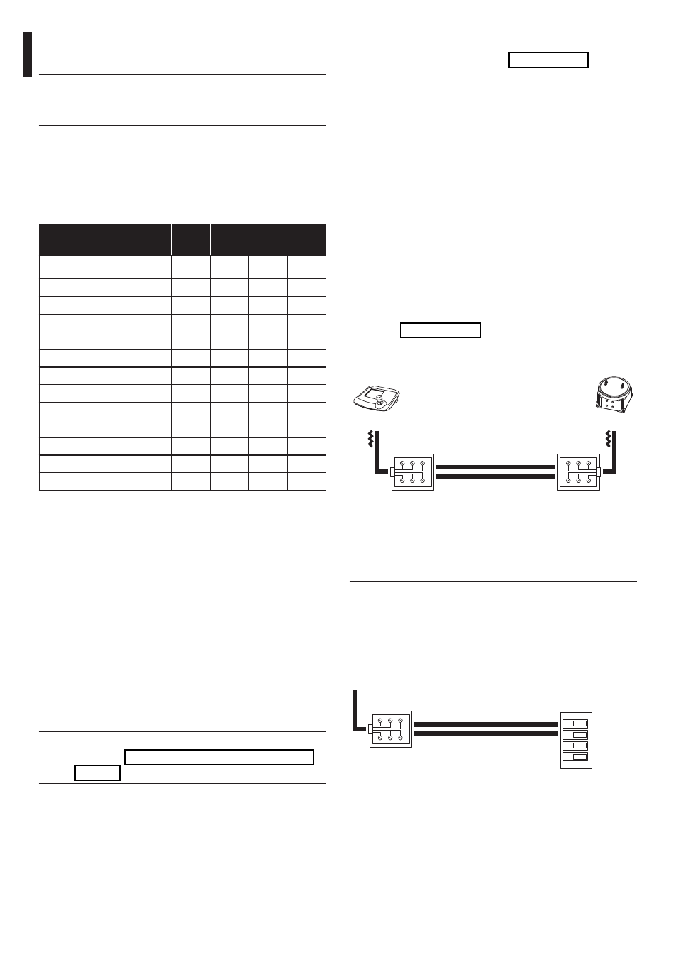
6.2.8 Connection with the control unit
The RJ11 connector (J1 in the Fig. 06, page 10)
supplied to the circuit enables the reception and
the transmission of digital data in RS232 or RS485
allowing a rapid connection of several units in case
of test runs or for the connection of conversion
interfaces available on the market (RS232-optical
fiber, etc.).
The final connection must be in RS485 mode with
DCJ, DCT and DCTEL keyboards. This mode allows to
reach a maximum distance of 1200m.
It is also possible to use control keyboards in Current
loop communication mode.
6.2.9 Connection with the RS485 line
The keyboards (DCJ, DCT and DCTEL) and the receiver
can be directly connected using the telephone
cable supplied by the manufacturer, using the RJ11
(J1 in the Fig. 06, page 10) connector present in
the circuit, as illustrated in the reference diagram
hereunder.
J1
DCT
White
Yellow
Black
Blue
Fig. 07
Communication mode RS485, max distance 1200m.
j
The receiver has the load inserted in
reception and is connected to line A or B on
the keyboard with the load inserted.
On the receiver side it is also possible to make a
simpler connection to terminals RX-485A and RX-
485B as in the following scheme.
TX-B
TX-A
RX-B
RX-A
RS485
TX 485A (White)
TX 485B (Yellow)
To RJ11
keyboard
connector
Receiver
clamps
Fig. 08
6.2.6 Communication speed protocol
setup
h
An inaccurate protocol or communication
speed selection can cause damages to the
receiver!
Used in digital transmission systems the EXDTRX3 /
EXDTRX324 receiver can communicate with a speed
varying from 300 to 38400 baud, depending on the
selected protocol.
• Dip switch: Switches 1, 2 and 8 of SW4 e 1 of SW6
PROTOCOL -
BAUD RATE
SW6
SW4
Dip 1
Dip 1
Dip 2
Dip 8
VIDEOTEC - 300 baud
OFF
ON
OFF
ON
VIDEOTEC - 1200 baud
OFF
OFF
ON
ON
VIDEOTEC - 9600 baud*
OFF
OFF
OFF
ON
VIDEOTEC - 19200 baud
OFF
ON
ON
ON
MACRO - 1200 baud
OFF
OFF
ON
OFF
MACRO - 9600 baud
OFF
OFF
OFF
OFF
MACRO - 19200 baud
OFF
ON
ON
OFF
MACRO - 38400 baud
OFF
ON
OFF
OFF
PELCO D - 2400 baud
ON
OFF
OFF
**
PELCO D - 4800 baud
ON
ON
OFF
**
PELCO D - 9600 baud
ON
OFF
ON
**
PELCO D - 19200 baud
ON
ON
ON
**
Tab. 01 * Default setup.
** Switch setting is indifferent; ON or OFF.
6.2.7 AUX3 / AUX4 auxiliary devices
setting
It is possible to set the functioning of the AUX3 /AUX4
auxiliary devices by setting dip 6 of switch SW4:
• Dip 6 of SW4 set to the OFF (default) position:
The operator has to press the control key in order
to activate the auxiliary device and then to press it
again in order to deactivate it.
• Dip 6 of SW4 set to the ON position: The auxiliary
device remain activated as long as the operator
keeps pressing the relevant control key.
j
AUX4 can be activated also on alarm
contact ("6.2.20 Operation mode of AUX4",
page 17).