Data terminal pins (pg-5j), Data terminal pins (pg‑5j) – Kenwood TM-D710GE User Manual
Page 103
99
Miscellaneous Topics 10
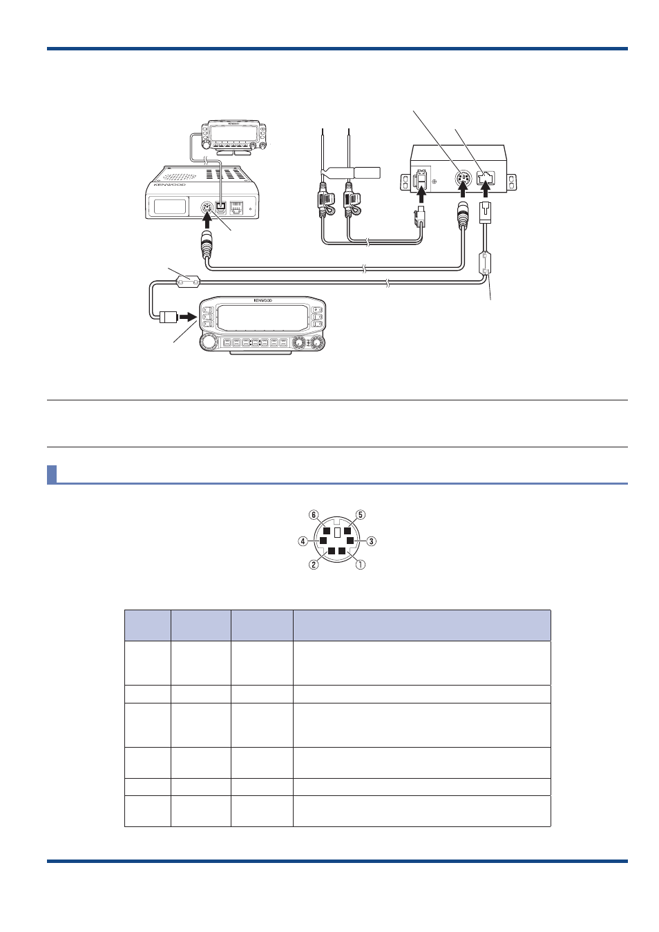
● Connection Example 2: Connecting RC-D710 to TM-D700A/E, TM-V708A
RC-D710
Modular plug cable
PG-5J
Black (-)
cable
Red (+)
cable
DC power cable
6-pin mini-DIN cable
DATA terminal
Panel jack
Panel jack
To 13.8 V DC power supply
or 12 V vehicle battery
DATA terminal
Transceiver
Line filter
Line filter
Fig. 10-2 Connecting RC‑D710 to TM‑D700A/E, TM‑V708A
Note:
◆ Excluding the situation of using the RC‑D710 as the operating panel for TM‑V71A/E, the RC‑D710 cannot operate
transceivers. Be sure to connect the control panel of the transceiver to the transceiver itself.
DATA Terminal Pins (PG-5J)
NC
PKS
PKD
GND
SQC
PR9
Fig. 10-3 DATA Terminal Pins (PG‑5J) Table
No.
Name
Input/
Output
Function
1
PKD
Output
TNC data output
2 Vp‑p/10 (9600 bps)
40 mVp-p/10 kΩ (1200 bps )
2
GND
‑
GND
3
PKS
Output
Data standby control signal output
Open collector
TX: Low level/ RX: High impedance
4
PR9
Input
TNC data input (both for 1200 bps and 9600 bps)
350 mVp-p to 600 mVp-p/10 kΩ
5
NC
‑
No connection
6
SQC
Input
Squelch control signal input (5 V CMOS level)
SQL Open: High level/ SQL Close: Low level