0 putting the actuator into operation, 1 configuring the control signal – ARI Armaturen ARI-PREMIO Plus EN User Manual
Page 40
Page 40
0040501004 5010
Operating and installation instructions
Thrust actuator ARI-PREMIO-Plus
6.0 Putting the actuator into operation
6.1 Configuring the control signal
The corresponding control signal (3-point or analogue, 0 to 10 V or 4 to 20 mA) must be
connected to the electronics prior to initialising the actuator (refer to 6.3 Initialisation).
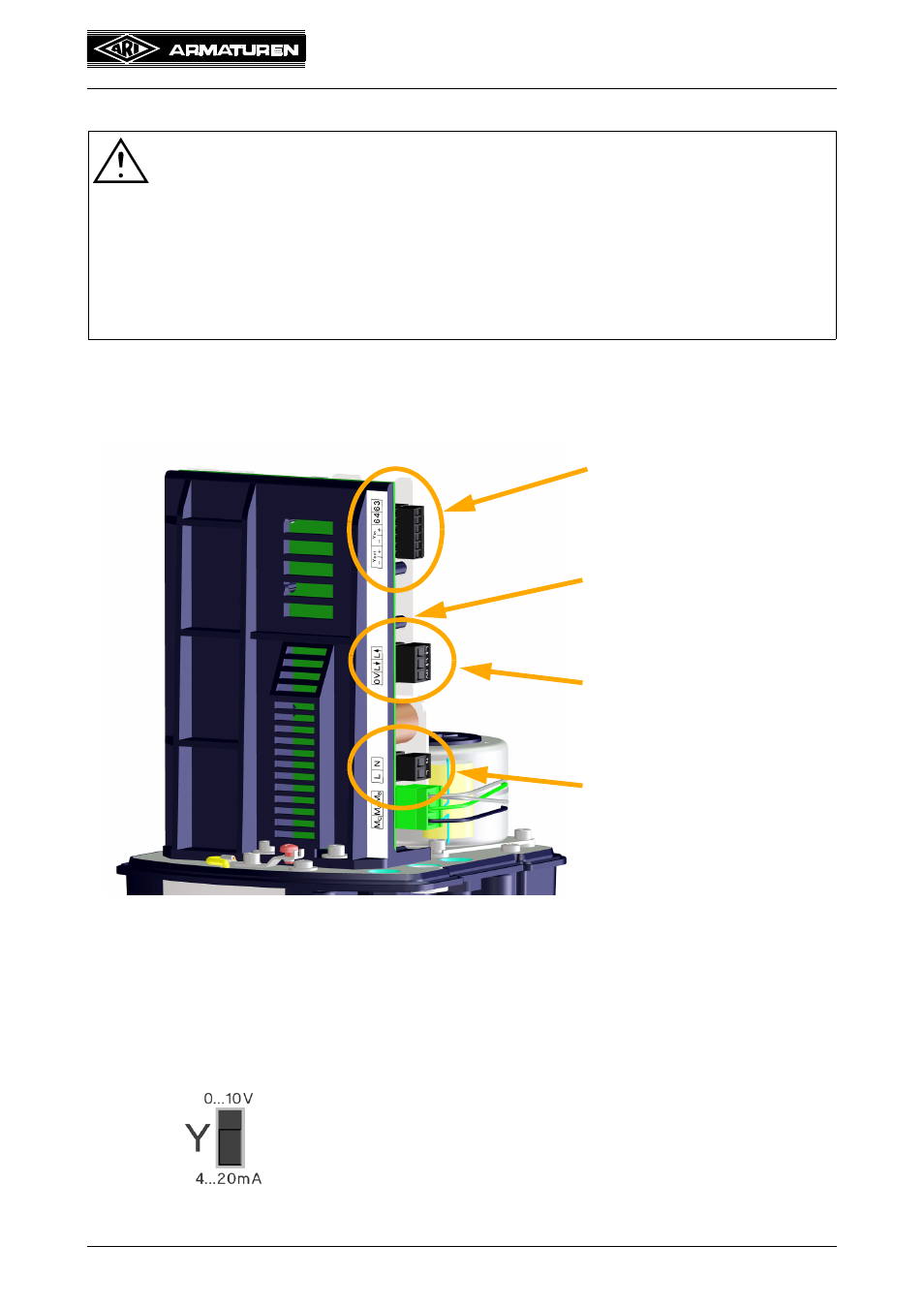
Fig. 27
If a control signal is not present at the analogue input during the initialisation run, the
electronics are set for 3-point control only. This is indicated by means of a continuously lit
LED that is mounted on the printed circuit board directly above the connector for the 3-point
signal.
If an analogue input control signal is present, the parameter switch must additionally be set
for 0 to 10 V or 4 to 20 mA on the operator panel.
ATTENTION !
All local safety instructions must be observed!
Before putting a new plant into operation or restarting a plant after repair or
modification, always make sure that:
- The power supply, control signal and ambient temperature coincide with the
technical data of the electronics.
- All work has been completed correctly!
The hood is mounted again following the completion of the adjustment work!
Fig. 28
The actuator can only be controlled with an analogue input
signal, and Yin signal failures detected, if an analogue input
control signal was detected at the analogue input during the
initialisation run!
0 - 10 V or 4 - 20 mA at Y
in
LED for 3-point control signal /
operation (on the back)
3-point control signal
Supply voltage