ARI Armaturen ARI-PREMIO Plus EN User Manual
Page 21
0040501004 5010
Page 21
Operating and installation instructions
Thrust actuator ARI-PREMIO-Plus
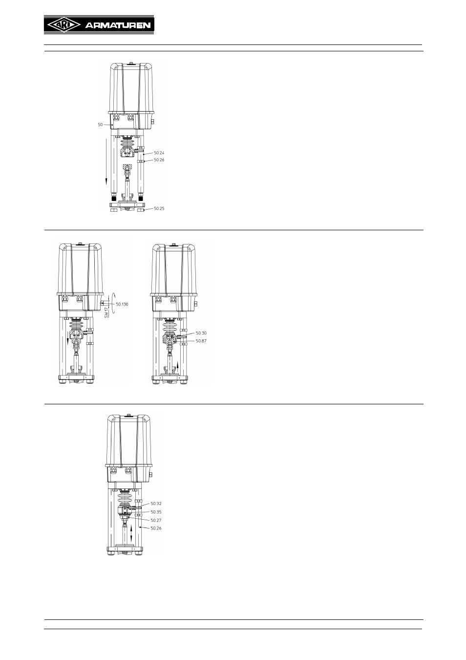
Bild 9-C
Fig. 9-C:
- Slip 2-ear clamp (pos. 50.26) onto a distance
column (pos. 50.24) press on very lightly in such a
way that one of the 2-ear clamps is situated above
the torsion safety feature (pos. 50.32) and the
other below.
- Place thrust actuator (pos. 50) with distance
columns onto valve and fix into position with two
self-locking hexagon nuts (pos. 50.25).
Bild 9-D/E
Fig. 9-D/E
- only 2,2-5 kN: Turn the manual operating device
(pos. 50.130) with a wrench (a/f 17) and use it to
move out the thrust actuator until the driving
spindle (pos. 50.30) comes to rest on the threaded
bush (pos. 50.87.
- only 12-15 kN: Fold out turning handle of
handwheel (pos. 50.12.1), slightly turn the
handwheel and press in the engaging button for
manual mode (only 12 - 15 kN) (button engages).
Having done this, move out the thrust actuator until
driving spindle (pos. 50.30) comes into contact with
threaded bush (pos. 50.87).
(refer to item 5.2.2 ARI-PREMIO 12 - 15 kN,
Fig. 6 ).
Bild 9-F
Fig. 9-F:
- Screw coupling (pos. 50.27) firmly into torsion
safety feature (pos. 50.32) and secure using grub
screw M6 (pos. 50.35).
- Move the valve to the lowest position.
- Press 2-ear clamps (pos. 50.26) into position
according to the stroke so they cannot slip, with the
bottom clamp in the lowest valve position located
directly below torsion safety feature (pos. 50.32)
and the top clamp in the highest valve position
located directly above the torsion safety feature.
- Move the valve to both travel positions and check
that it reaches them reliably.
- Fold turning handle of handwheel (pos. 50.12.1)
back in.
- Make the electrical connection (see point “5.4
Electrical connection”). The engaging button for
manual mode (only 12 - 15 kN) disengages when
the motor starts up.
- For starting up refer to point 6.0.
turn