3 installation instructions for mounting to valves – ARI Armaturen ARI-PREMIO Plus EN User Manual
Page 18
Page 18
0040501004 5010
Operating and installation instructions
Thrust actuator ARI-PREMIO-Plus
5.3 Installation instructions for mounting to valves
5.3.1 Mounting for valve-lift up to 30 mm (yoke version)
- Screw coupling (pos. 50.27) out of torsion safety feature (pos. 50.32) of thrust actuator (not
illustrated).
- Position valve cone approximately in mid lift position.
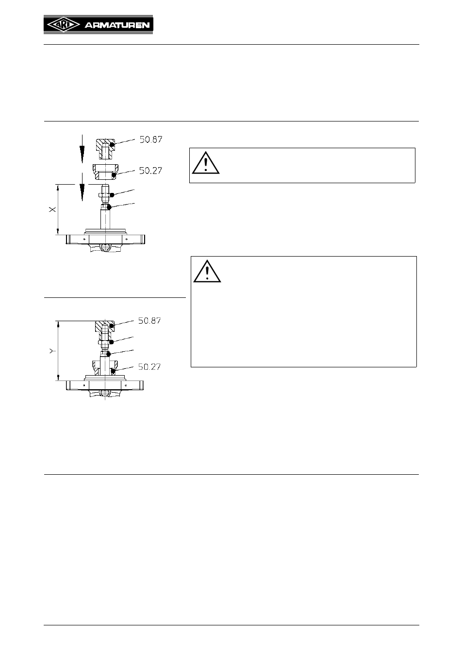
Fig. 8-A
Fig. 8-A:
- Turn flat hexagon nut if not mounted yet on valve stem.
Fig. 8-A/B:
- Slip coupling (pos. 50.27) over valve stem.
- Screw threaded bush (pos. 50.87) matching the valve onto
the valve stem in accordance with setting dimension (Y)
and lock with hexagon nut.
- Setting dimension (Y) for fitting-projection (X) 60 and
83mm = 102mm
Fig. 8-B
Hexagon nut
Valve stem
ATTENTION !
X = 60/83mm --> Y = 102mm
(+2mm)
X = 98mm --> Y = 116mm
(+2mm)
ATTENTION !
Setting dimension (Y) and fitting-projection (X)
are measured with inserted valve stem. This
means for
- 2-way valves at closed valve,
- 3-way valves with mixing plug at closed way B,
- 3-way valves with diverting plug at closed way
A
After measuring put the valve plug back in the
mid lift position!
Hexagon nut
Valve stem