ARI Armaturen ARI-PREMIO Plus EN User Manual
Page 28
Page 28
0040501004 5010
Operating and installation instructions
Thrust actuator ARI-PREMIO-Plus
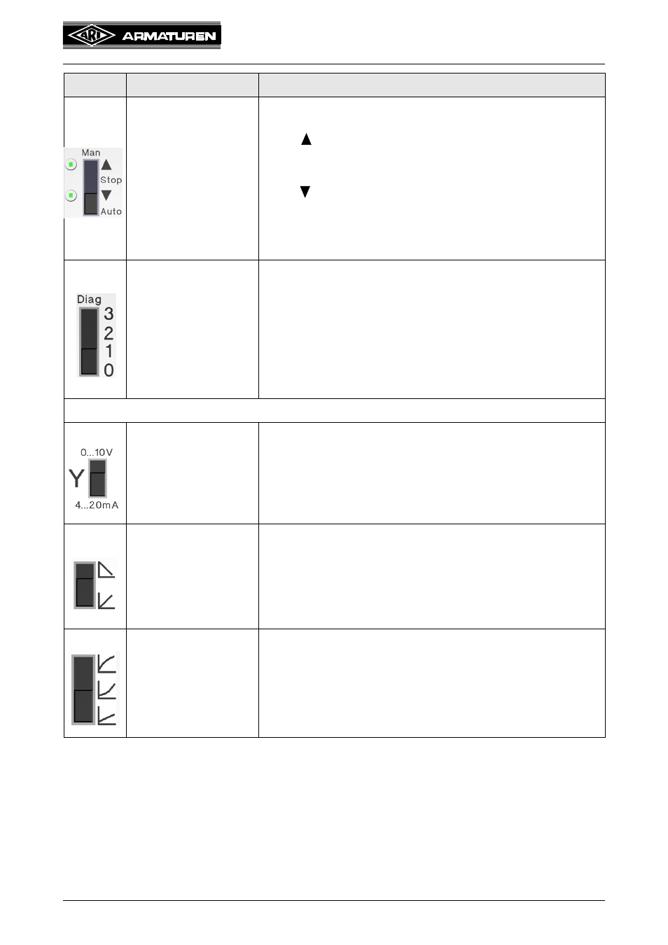
Local operation of the
actuator
This 4-step slide switch takes priority over all other inputs and
system states.
In the
position (up), the driving spindle is inserted into the
gearbox until the corresponding travel switch is actuated.
In the "Stop" position, the motor is de-energised.
In the
position (down), the driving spindle is withdrawn from
the gearbox until the corresponding travel switch is actuated.
In the "Auto" position, the actuator follows the control signal.
Two LEDs indicate the direction of the driving spindle.
Sensitivity setting for
the diagnostic signal
3 = Comprises step 1 and step 2 as well as other function
checks (e.g. voltage and frequency faults)
2 = Internal temperature exceeds 80°C for more than one
hour or oscillation detected
1 = Moisture detected inside the actuator for more than one
hour or maximum hysteresis band active for more than
one hour
0 = Off
Configuration switches for the analogue control signal
Voltage or current
signal
This slide switch can be used to select a 0 to 10 V voltage
signal or a 4 to 20 mA current signal. The setting applies to
both the control signal input and output.
Invert control signal
This slide switch inverts the analogue control signal (input and
output).
Switch up:
Inverted: 0 V or 4 mA = driving spindle retracted
Switch down:
Normal: 0 V or 4 mA = driving spindle extended
Characteristics
This slide switch sets three different characteristics that define
the relationship between the input signal and the valve
position (refer also to 5.6.7 Characteristics). The three
characteristics can be described as "linear", "equal-
percentage" and "inverse equal-percentage".
Switch
Meaning
Description / explanation