Annun, Color, Type – Red Lion PAX2S User Manual
Page 16: Assign, Analog, Output, Update, Analog output parameters ( analog )
16
SETPOINT ANNUNCIATOR
nor
rEv
FLASH
OFF
The nor mode displays the corresponding setpoint annunciators of “on”
alarm outputs. The rEv mode displays the corresponding setpoint annunciators
of “off” alarms outputs. The FLASH mode flashes the corresponding setpoint
annunciators of “on” alarm outputs. The OFF mode disables display setpoint
annunciators.
LINE 1 CHANGE COLOR
NO CHG
GrEEN
OrANGE
rEd
GrnOrG
rEdOrG
rEdGrn
LINE 1
This parameter allows the Line 1 Display to change color, or alternate
between two colors, when the alarm is activated. When multiple alarms are
programmed to change color, the highest numbered active alarm (S4-S1)
determines the display color.
The NO CHG selection will maintain the color displayed prior to the alarm
activation. The LINE 1 selection sets the display to the Display (Line 1)
Color (Color).
Annun
nor
Sn
Color
NO CHG
Sn
tYPE
4-20
AnL
ASSIGN
NONE
AnL
ANALOG
0
LO
ANALOG
10000
HI
Analog
Output Type
Analog Output
Assignment
Analog Low
Scale Value
Analog High
Scale Value
OUtPUt
ANALOG
UPdAtE
0.0
AnL
Analog Update
Time
Pro
OUtPUt
Pro
NO
F1
F2
P
D
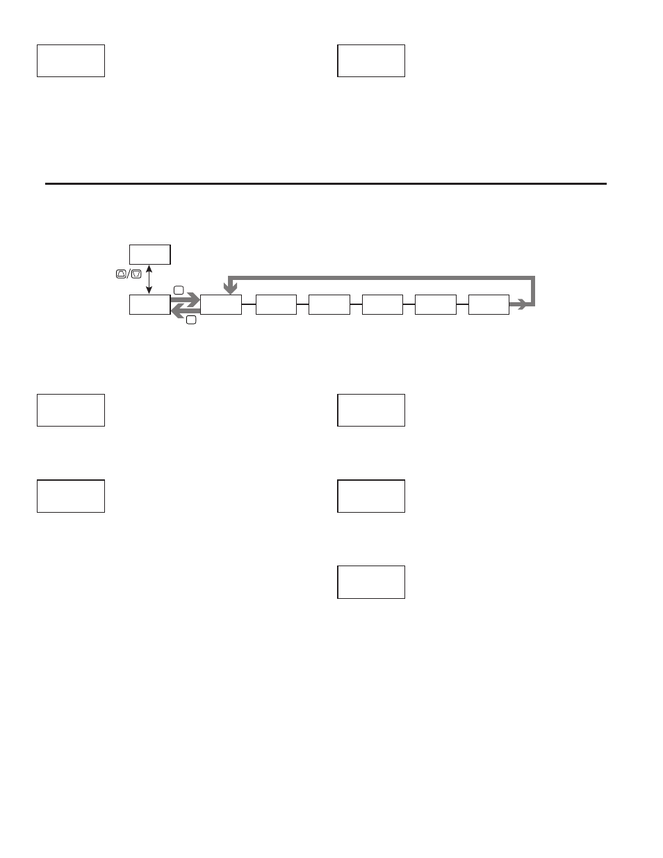
ANALOG OUTPUT PARAMETERS (ANALOG)
This section is only accessible with the optional PAXCDL Analog card installed (see Ordering Information).
ANALOG OUTPUT TYPE
4-20 0-10 0-20
Enter the analog output type. For 0-20 mA or 4-20 mA use terminals 18 and
19. For 0-10 V use terminals 16 and 17. Only one range can be used at a time.
ANALOG OUTPUT ASSIGNMENT
NONE
rEL
GrOSS
tOtAL
HI
LO
S1
S2
S3
S4
Enter the source for the analog output to retransmit:
NONE
= Manual Mode operation. (See Serial RLC Protocol in the
Communications Port module).
rEL
=
Relative (net) Input Value. The Relative Input Value is the
Gross (Absolute) Input Value that includes the Display
Tare (Offset) Value.
GrOSS
= Gross (Absolute) Input Value. The Gross Input Value is
based on the Input (Analog) module dSP and INP entries.
tOtAL
= Totalizer Value
HI
=
Maximum Display Value
LO
=
Minimum Display Value
S1
-S4 = Setpoint Values
ANALOG LOW SCALE VALUE
-199999
to
999999
Enter the Display Value that corresponds to 0 mA (0-20 mA) , 4 mA (4-20
mA) or 0 VDC (0-10 VDC).
ANALOG HIGH SCALE VALUE
-199999
to
999999
Enter the Display Value that corresponds to 20 mA (0-20 mA) , 20 mA (4-20
mA) or 10 VDC (0-10 VDC).
ANALOG UPDATE TIME
0.0
to
10.0
Enter the analog output update rate in seconds. A value of 0.0 allows the
meter to update the analog output at the ADC Conversion Rate.
tYPE
4-20
AnL
ASSIGN
NONE
AnL
ANALOG
0
LO
ANALOG
10000
HI
UPdAtE
0.0
AnL