Range, Rate, Decpnt – Red Lion PAX2S User Manual
Page 10: Round, Tare, Filter, Band, Points, Input, Input )
10
Pro
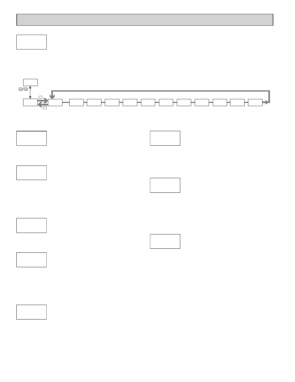
INPUt
Pro
NO
INPUt
ANALOG
rAtE
5
INP
Input Update
Rate
dECPNt
0.00
INP
Decimal
Resolution
tArE
0.00
INP
Display
Tare Value
round
0.01
INP
Rounding
Increment
FILtEr
1.00
INP
Digital
Filtering
bANd
0.10
INP
Filter Band
POINtS
2
INP
Scaling
Points
StYLE
KEY
INP
Scaling
Style
INPUt
0.000
n
Input n
Value
rANgE
0.024v
INP
Input Range
dISPLY
0.00
n
Display n
Value
F1
F2
P
D
i
npuT
p
arameTers
(INPUt)
ANALOG INPUT PARAMETERS (
ANALOG
)
This section details the programming for the analog input.
INPUT RANGE
0.024u
0.24u
Select the desired input range.
INPUT UPDATE RATE (/SEC)
5
10
20
40
80
160
Select the ADC conversion rate (conversions per second). The selection does
not affect the display update rate, however it does affect setpoint and analog
output response time. The default factory setting of 5 is recommended for most
applications. Selecting a fast update rate may cause the display to appear very
unstable.
DECIMAL RESOLUTION (Display Units)
0
0.00
0.0000
0.0
0.000
Select desired display resolution.
ROUNDING INCREMENT
1
2
5
10
20
50
100
Rounding selections other than one, cause the Input Display to ‘round’ to the
nearest rounding increment selected (ie. rounding of ‘5’ causes 122 to round to
120 and 123 to round to 125). Rounding starts at the least significant digit of the
Input Display. Remaining parameter entries (scaling point values, setpoint
values, etc.) are not automatically adjusted to this display rounding selection.
DISPLAY TARE (Offset) Value
-19999
to
99999
The Display Tare(offset) Value is the difference between the Gross (absolute)
Display value and the Relative (net) Display value for the same input level. The
meter will automatically update this value after each Zero Display. The Display
Tare Value can be directly keyed-in to intentionally add or remove display
offset. See Relative/Gross Display and Zero Display explanations in the Input
Parameters - User Input Module.
DIGITAL FILTERING
0.00
to
25.00
seconds
The input filter setting is a time constant expressed in hundredths of a second.
The filter settles to 99% of the final display value within approximately 3 time
constants. This is an Adaptive Digital Filter which is designed to steady the
Input Display reading. A value of ‘0’ disables filtering.
FILTER BAND
0
to
2500
display units
The digital filter will adapt to variations in the input signal. When the
variation exceeds the input filter band value, the digital filter disengages. When
the variation becomes less than the band value, the filter engages again. This
allows for a stable readout, but permits the display to settle rapidly after a large
process change. The value of the band is in display units. A band setting of ‘0’
keeps the digital filter permanently engaged.
SCALING POINTS
2
to
16
Linear - Scaling Points (2)
For linear processes, only 2 scaling points are necessary. It is recommended
that the 2 scaling points be at opposite ends of the input signal being applied.
The points do not have to be the signal limits. Display scaling will be linear
between and continue past the entered points up to the limits of the Input Signal
Jumper position. Each scaling point has a coordinate-pair of Input Value (INPUt
n
) and an associated desired Display Value (dISPLY n).
Nonlinear - Scaling Points (Greater than 2)
For non-linear processes, up to 16 scaling points may be used to provide a
piece-wise linear approximation. (The greater the number of scaling points used,
the greater the conformity accuracy.) The Input Display will be linear between
scaling points that are sequential in program order. Each scaling point has a
coordinate-pair of Input Value (INPUt n) and an associated desired Display Value
(dISPLY n). Data from tables or equations, or empirical data can be used to derive
the required number of segments and data values for the coordinate pairs.
Several linearization equations are available within Crimson software.
rANgE
0.024u
INP
1
3
2
4
rAtE
5
INP
1
3
2
4
dECPNt
0.00
INP
1
3
2
4
round
0.01
INP
1
3
2
4
tArE
0.00
INP
1
3
2
4
FILtEr
1.00
INP
1
3
2
4
bANd
0.10
INP
1
3
2
4
POINtS
2
INP
INPUT SELECT
ANALOG
USEr
Select the Input to be programmed.
INPUt
ANALOG