Bn-dev, Output ), Utput – Red Lion PAX2S User Manual
Page 14: Arameters, Setpoint output parameters ( setpnt ), Output, Select, Assign, Setpnt, Action
14
OUtPUt
SEtPNt
SELECt
S1
SPt
Setpoint
Select
ASSIGN
NONE
S
n
Setpoint
Assignment
SEtPNt
100
S
n
Setpoint
Value
ACtION
NO
S
n
Setpoint
Action
bn-dEU
0
S
n
Band/
Deviation
Value
HYStEr
2
S
n
Hysteresis
Value
t-ON
0.0
S
n
On Time
Delay
t-OFF
0.0
S
n
Off Time
Delay
n = Setpoint Number (1-4)
LOGIC
nor
S
n
Output
Logic
StndbY
NO
S
n
Setpoint
Standby
Operation
rESEt
Auto
S
n
Reset
Action
Annun
nor
S
n
Setpoint
Annunciator
Color
NO CHG
S
n
Line 1
Change Color
Pro
OUtPUt
Pro
NO
F1
F2
P
D
O
uTpuT
p
arameTers
(OUtPUt)
SETPOINT SELECT
S1
S2
S3
S4
Select the Setpoint output to be programmed. The “Sn” in the following
parameters will reflect the chosen setpoint number. After the chosen setpoint is
completely programmed, the display returns to the Setpoint Select menu. Repeat
steps for each setpoint to be programmed.
The number of outputs available is setpoint output card dependent (2 or 4). If
no output card is installed, programming is still available for all 4 setpoints. This
allows the Line 1 color change feature to provide a visual indication when a
setpoint value has been reached, even if no setpoint output is being used.
SETPOINT ASSIGNMENT
NONE
rEL
GrOSS
tOtAL
Selects the meter value to be used to trigger the Setpoint Alarm. The rEL
setting will cause the setpoint to trigger off of the relative (net) input value. The
relative input value is the absolute input value plus the Display Tare (Offset)
Value. The GrOSS setting will cause the setpoint to trigger off of the gross
(absolute) input value. The gross input value is based on the Input (Analog)
module dSP and INP entries.
SETPOINT ACTION
NO
Ab-HI
Ab-LO
AU-HI
AU-LO
dE-HI
dE-LO
bANd
bNdIn
totLo
totHi
Enter the action for the selected setpoint (alarm output). See Setpoint Alarm
Figures for a visual detail of each action. The Setpoint Actions that pertains to
the total is only active when the Setpoint Assignment is set to tOtAL.
NO
= No Setpoint Action
Ab-HI
= Absolute high, with balanced hysteresis
Ab-LO
= Absolute low, with balanced hysteresis
AU-HI
= Absolute high, with unbalanced hysteresis
AU-LO
= Absolute low, with unbalanced hysteresis
dE-HI
= deviation high, with unbalanced hysteresis
dE-LO
= deviation low, with unbalanced hysteresis
bANd
= Outside band, with unbalanced hysteresis
bNdIn
= Inside band, with unbalanced hysteresis
totLo
= Lower 6 digits of 9 digit Totalizer, with unbalanced hysteresis
totHi
= Upper 6 digits of 9 digit Totalizer, with unbalanced hysteresis
SETPOINT VALUE
-199999
to
999999
Enter desired setpoint alarm value. Setpoint values can also be entered in the
Display Mode during Program Lockout when the setpoint is programmed as
Entr
in the Display (Line 2) Access parameters. The decimal point position is
determined by the Setpoint Assignment value.
BAND/DEVIATION VALUE
-199999
to
999999
This parameter is only available in band and deviation setpoint actions. Enter
desired setpoint band or deviation value. When the Setpoint Action is
programmed for Band, this value can only be a positive value.
HYSTERESIS VALUE
1
to
65000
Enter desired hysteresis value. See Setpoint Alarm Figures for visual
explanation of how setpoint alarm actions (balanced and unbalanced) are
affected by the hysteresis. When the setpoint is a control output, usually balanced
hysteresis is used. For alarm applications, usually unbalanced hysteresis is used.
For unbalanced hysteresis modes, the hysteresis functions on the low side for
high acting setpoints and functions on the high side for low acting setpoints.
Note: Hysteresis eliminates output chatter at the switch point, while time delay
can be used to prevent false triggering during process transient events.
SELECt
S1
SPt
ASSIGN
NONE
Sn
ACtION
NO
Sn
SEtPNt
100
Sn
bn-dEV
0
dn
HYStEr
2
Sn
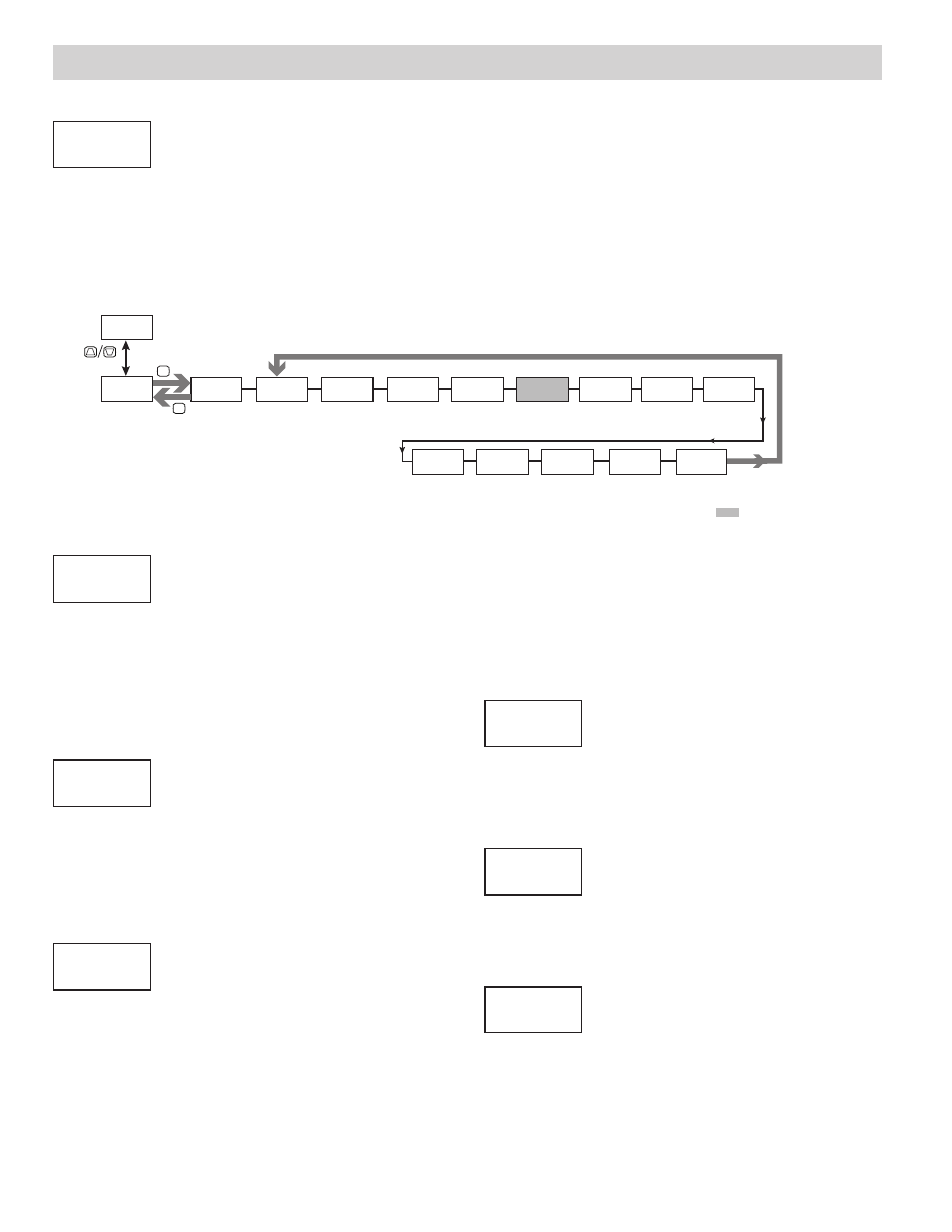
SETPOINT OUTPUT PARAMETERS (SEtPNt)
This section details the programming for the setpoints. To have output capabilities, a setpoint Plug-in card needs to be installed into the PAX2S (see Ordering
Information). Depending on the card installed, there will be two or four setpoint outputs available. If no output card is installed, programming for the setpoints is still
available. An Exchange Parameter Lists feature for setpoint values is explained in User Input programming.
The Setpoint Assignment and Setpoint Output Action determine certain setpoint feature availability. The Setpoint Parameter Availability chart illustrates this.
OUTPUT SELECT
SEtPNt
ANALOG
Select the Setpoint or Analog output to be programmed. The Analog output selection
only appears if an analog output plug-in card is installed in the meter.
OUtPUt
SEtPNt
Setpoint Action dependent