T-on, T-off, Logic – Red Lion PAX2S User Manual
Page 15: Reset, Stndby, Nor rev, Auto latch1s latch2, No yes, Auto
15
ON TIME DELAY
0.0
to
3275.0
seconds
Enter the time value in seconds that the alarm is delayed from turning on after
the trigger point is reached. A value of 0.0 allows the meter to update the alarm
status per the response time listed in the Specifications. When the output logic
is rEv, this becomes off time delay. Any time accumulated at power-off resets
during power-up.
OFF TIME DELAY
0.0
to
3275.0
seconds
Enter the time value in seconds that the alarm is delayed from turning off after
the trigger point is reached. A value of 0.0 allows the meter to update the alarm
status per the response time listed in the Specifications. When the output logic
is rEv, this becomes on time delay. Any time accumulated at power-off resets
during power-up.
OUTPUT LOGIC
nor rEv
Enter the output logic of the alarm output. The nor logic leaves the output
operation as normal. The rEv logic reverses the output logic. In rEv, the alarm
states in the Setpoint Alarm Figures are reversed.
RESET ACTION
Auto
LAtCh1s
LAtCh2
Enter the reset action of the alarm output.
Auto
= Automatic action; This action allows the alarm output to automatically
reset at the trigger points per the Setpoint Action shown in Setpoint Alarm
Figures. The “on” alarm may be manually reset immediately by a front panel
function key or user input.The alarm remains reset until the trigger point is
crossed again.
LAtCh1
= Latch with immediate reset action; This selection latches the alarm
output on at the trigger point per the Setpoint Action shown in Setpoint Alarm
Figures. Latch means that the alarm output can only be turned off by front
panel function key or user input manual reset, serial reset command or meter
power cycle. When the user input or function key is activated (momentary or
maintained), the corresponding “on” alarm output is reset immediately and
remains off until the trigger point is crossed again. (Previously latched alarms
will be off if power up Display Value is lower than setpoint value.)
LAtCh2
= Latch with delay reset action; This selection latches the alarm output
on at the trigger point per the Setpoint Action shown in Setpoint Alarm
Figures. Latch means that the alarm output can only be turned off by front
panel function key or user input manual reset, serial reset command or meter
power cycle. When the user input or function key is activated (momentary or
maintained), the meter delays the reset event until the corresponding “on”
alarm output crosses the trigger off point. (Previously latched alarms are off
if power up Display Value is lower than setpoint value. During a power cycle,
the meter erases a previous Latch 2 reset if it is not activated at power up.)
SETPOINT STANDBY OPERATION
NO YES
When YES, the alarm is disabled (at power up) until the trigger point is
crossed.
t-ON
0.0
Sn
t-OFF
0.0
Sn
LOGIC
nor
Sn
rESEt
Auto
Sn
StndbY
NO
Sn
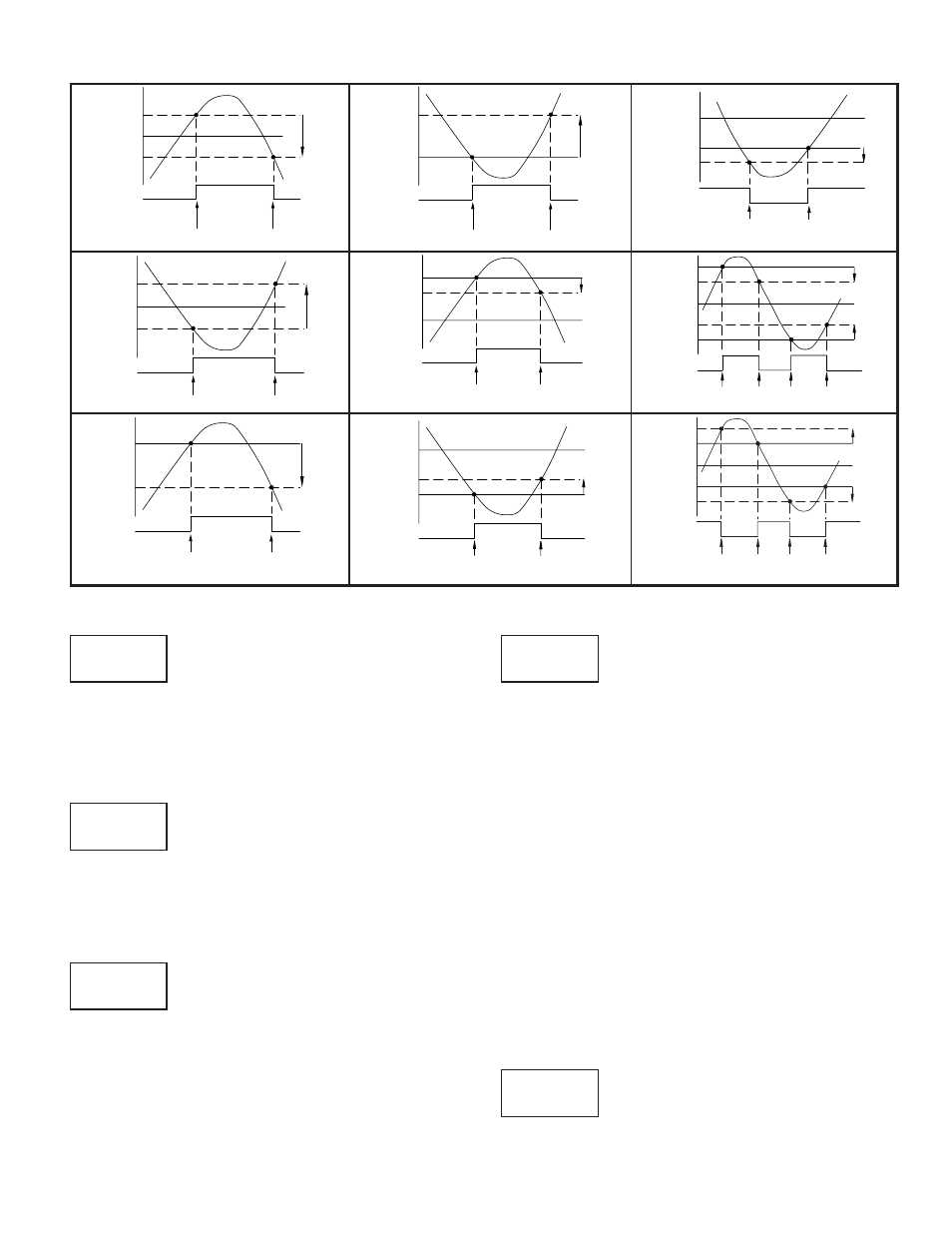
Setpoint Alarm Figures
With reverse output logic
rEv
, the below alarm states are opposite.
ALARM
STATE
OFF
ON
Hys
SP + Hys
SP
OFF
TRIGGER POINTS
ALARM
STATE
OFF
ON
Hys
SP - Bnd
SP
OFF
SP + Bnd
ON
OFF
Hys
TRIGGER POINTS
Absolute Low Acting (Unbalanced Hys) =
AU-LO
Band Outside Acting =
bANd
ALARM
STATE
OFF
ON
Hys
SP + ½Hys
SP
SP - ½Hys
OFF
TRIGGER POINTS
ALARM
STATE
OFF
ON
Hys
SP + Dev
SP
OFF
TRIGGER POINTS
ALARM
STATE
ON
OFF
Hys
SP - Bnd
SP
ON
SP + Bnd
OFF
ON
Hys
TRIGGER POINTS
Absolute Low Acting (Balanced Hys) =
Ab-LO
Deviation High Acting (Dev
> 0) =
dE-HI
Band Inside Acting =
bNdIn
ALARM
STATE
OFF
ON
Hys
SP
SP - Hys
OFF
TRIGGER POINTS
ALARM
STATE
OFF
ON
Hys
SP - Dev
SP
OFF
TRIGGER POINTS
ALARM
STATE
ON
OFF
Hys
SP + (-Dev)
SP
ON
TRIGGER POINTS
Absolute High Acting (Unbalanced Hys) =
AU-HI
This is also for Totalizer alarms:
totLO
,
totHI
Deviation Low Acting (Dev > 0) =
dE-LO
Deviation High Acting (Dev
< 0) =
dE-HI
ALARM
STATE
OFF
ON
Hys
SP + ½Hys
SP
SP - ½Hys
OFF
TRIGGER POINTS
Absolute High Acting (Balanced Hys) =
Ab-HI