Connector signals, Figure 36, Pins for 17-pin m23 connector – Vaisala WMT700 User Manual
Page 83: Table 25, Pin-out for 17-pin m23 connector
Chapter 4 ________________________________________________________________ Installation
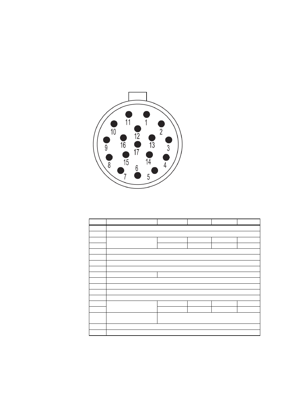
Connector Signals
Figure 36 and Table 25 below describe the pin-out of the 17-pin
M23 connector as seen from the outside. The serial output type of
COM2 depends on the sensor configuration. Analog outputs are
always available from the connector.
1103-061
Figure 36
Pins for 17-Pin M23 Connector
Table 25
Pin-Out for 17-Pin M23 Connector
Pin
Description
RS-232
RS-422
RS-485
SDI-12
1
Operating Power Supply
2
Analog output AOUT2, Wind Direction
3
COM2
RS232Rx
Rx–
Rx–
-
4
RS232Tx
Tx–
Tx–
Data
5
Heater Power Supply
6
Heater Power Supply
7
Heater Power Supply Ground
8
Heater Power Supply Ground
9
COM1 (Service Port) RS-485, B
10
COM1 and COM2 Communication Ports Ground
11
Operating Power Supply Ground
12
Analog Output Ground
13
Analog Output AOUT1, Wind Speed
14
COM2
-
Tx+
Tx+
-
15
-
Rx+
Rx+
-
16
COM1
(Service port)
RS-485+
17
Reference Input for AOUT2 (simulated potentiometer)
Shield Enclosure Ground
VAISALA ________________________________________________________________________ 81