Table 34, Analog output connections – Vaisala WMT700 User Manual
Page 106
User's Guide ______________________________________________________________________
Differences between WMT700 and
WS425 Analog Output Signals
WMT700 pin connections differ from the connections of WS425
in that wind speed signal output, both voltage and frequency
signals, appears on WMT700 pin 13.
NOTE
WMT700 analog outputs must be configured according to the appropriate
analog output mode, which is either voltage, frequency, or potentiometer.
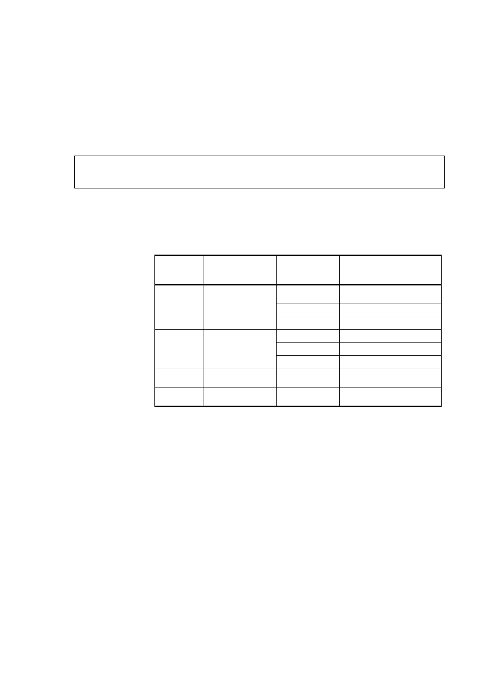
Table 34 below lists the analog output connections for WMT700
and WS425 connector pins.
Table 34
Analog Output Connections
WMT700
Connector
Pin
WMT700 Signal
Description
Voltage Output WS425 Connector Pin,
Wire Color
13
Analog Output
AOUT1, Wind
Speed
Voltage
15, Violet (connect pin 14
to ground)
Current
not available
Frequency
14, Pink
2
Analog Output
AOUT2, Wind
Direction
Voltage
13, Gray
Current
not available
Potentiometer
13, Gray
17
Reference Input
for AOUT2
Potentiometer
12, White
12
Analog Output
Ground
All modes
1, Black (common with
supply ground)
104 __________________________________________________________________ M211095EN-E