Wiring, Table 2, Wiring pins – Vaisala GMP343 User Manual
Page 26: Warning
User’s Guide ______________________________________________________________________
24 ___________________________________________________________________M210514EN-E
Wiring
As it is shipped from the factory, the measurement range and output of the
GMP343 are scaled according to the order form completed by the
customer. The unit is calibrated at the factory. The device is ready for use
when the wiring is done and power is switched on.
GMP343 can be connected to a PC using an optional PC connection cable,
see
.
For more information on serial commands, see
.
WARNING
Make sure that the main power is switched off before making any
electrical connections.
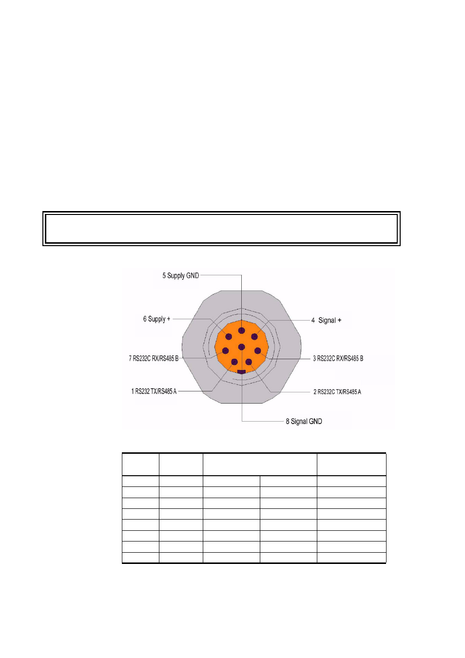
Table 2
Wiring Pins
Pin
Wire
Serial signal (RS-232 or 2-
Wire RS-485 interface)
Analog signal
1
White
RS232C: TX
RS485: A(+)
-
2
Brown
RS232C: TX
RS485: A(+)
-
3
Green
RS232C: RX
RS485: B(-)
-
4
Yellow -
-
Signal
+
5
Grey
Supply GND
Supply GND
Supply GND
6
Pink
+11...36 V DC +11...36 V DC +11...36 V DC
7
Blue
RS232C: RX
RS485: B(-)
-
8
Shield
-
-
Signal GND