Connectors and pinouts, Port a – Ag Leader GPS 5200 User Guide User Manual
Page 30
3 Installing the Receiver
28 GPS 5200 Receiver User Guide
Connectors and pinouts
Use the following pinout information if you need to wire a cable for use
with the GPS 5200 receiver:
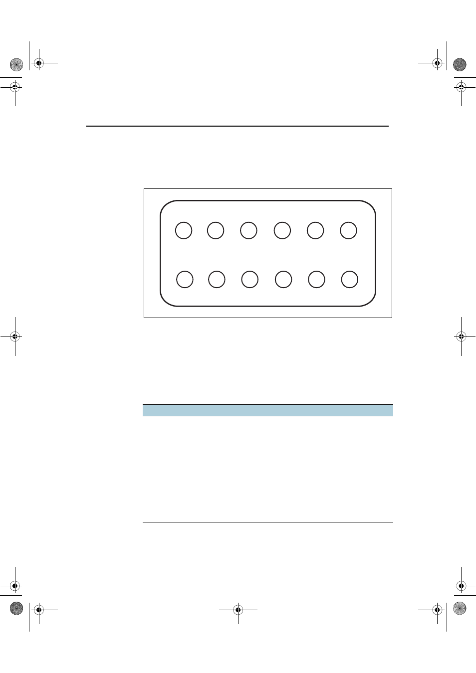
Port A
Port A on the receiver has a 12-pin Deutsch DTM connector. For cables,
use the mating connector, Deutsch part number DTM06-12SA.
Viewed from outside the receiver, the Port A connector is on the left. It
is the port that is typically used to connect to an Autopilot system.
Pin
Name/Function
Comments
1
CAN A High I/O
2
Port 1 RS232 Tx OUT
When held to ground during power up,
puts unit into Monitor mode
3
Port 1 RS232 Rx IN
4
PPS OUT
5
Signal GND
Used for RS232 and other signals.
Should not be connected to
V– (battery negative)
6
Port 1 RTS OUT
7
Radar OUT / Alarm OUT
2
1
3
4
5
6
7
8
9
10
11
12
GPS5200_1A_UserGuide_ENG.book Page 28 Friday, December 19, 2008 12:57 PM
- Yield Monitor 2000 Operators Manual (202 pages)
- Yield Monitor 2000 Quick Reference Sheets (2 pages)
- PF3000 Harvest & Application Operators Manual (259 pages)
- PF3000 Cotton Yield Monitor Operators Manual (149 pages)
- PF3000/PF3000Pro Harvest Master Mode Operators Manual (13 pages)
- PF3000/PF3000Pro Advanced Light Bar Operators Manual (59 pages)
- PF3000/PF3000Pro Harvest Mode Quick Reference Sheets (2 pages)
- PF3000/PF3000Pro Cotton Harvest Quick Reference Sheets (2 pages)
- PF3000/PF3000Pro Site Verification Mode Quick Reference Sheets (2 pages)
- PF3000/PF3000Pro Rawson Accu-Rate Direct Drive Quick Reference Sheets (9 pages)
- PF3000/PF3000Pro Rawson and New Leader Controllers Quick Reference Sheets (4 pages)
- PF3000/PF3000Pro Raven Controllers (with serial port) Quick Reference Sheets (4 pages)
- PF3000/PF3000Pro Raven Controllers (without serial port) Quick Reference Sheets (3 pages)
- PF3000/PF3000Pro Mid-Tech Controllers Quick Reference Sheets (4 pages)
- PF3000/PF3000Pro Dickey-john Land Manager Quick Reference Sheets (4 pages)
- PF3000/PF3000Pro Dickey-john Seed Manager Quick Reference Sheets (3 pages)
- PF3000/PF3000Pro Hiniker 8100 and 8150 Controllers Quick Reference Sheets (3 pages)
- PF3000/PF3000Pro Hiniker 8605 Controller Quick Reference Sheets (4 pages)
- PF3000/PF3000Pro TeeJet 844 Controller Quick Reference Sheets (4 pages)
- PF3000/PF3000Pro Flexicoil Flex Control Quick Reference Sheets (4 pages)
- PF3000/PF3000Pro Microtrack MT9000/Hardi 3500 Controllers Quick Reference Sheets (4 pages)
- PF3000/PF3000Pro Krohne Flow Meter Quick Reference Sheets (3 pages)
- PF3000/PF3000Pro Shaft Speed Sensor Quick Reference Sheets (3 pages)
- PF3000Pro Harvest & Application Operators Manual (294 pages)
- PF3000Pro Cotton Yield Monitor Operators Manual (168 pages)
- PFadvantage Harvest & Application Operators Manual (264 pages)
- PFadvantage Cotton Yield Monitor Operators Manual (166 pages)
- InSight Harvest Mode (4 pages)
- InSight Site Verification Mode (4 pages)
- InSight Tillage Mode (8 pages)
- InSight Flow Meter (9 pages)
- InSight Spinner Spreader (14 pages)
- InSight Strip-Till (10 pages)
- InSight NORAC UC5 (4 pages)
- InSight Direct Injection (4 pages)
- InSight Rawson and New Leader Controllers (5 pages)
- InSight Raven Serial, NL Mark V, SP6 (5 pages)
- InSight Mid-Tech Controllers (5 pages)
- InSight Direct Command Liquid (19 pages)
- Integra DirectCommand Clutch Control Quick Reference Guides (1 page)
- InSight SC Hydraulic Seed Rate Control (4 pages)
- InSight SC Stepper Seed Rate Control (3 pages)
- InSight SC KINZE PMM (3 pages)
- InSight SC Seed Tube Monitor (STMM) (16 pages)
- InSight Ver.8.0 Users Manual (342 pages)