Vt quick reference guide, Quick reference guide, Can power module – Ag Leader Versa DirectCommand ISOBUS Quick Reference Guides User Manual
Page 7: Battery, Can a relay can b relay
7
VT Quick Reference Guide
Quick Reference Guide
AL: 2006300 - ENG Rev C
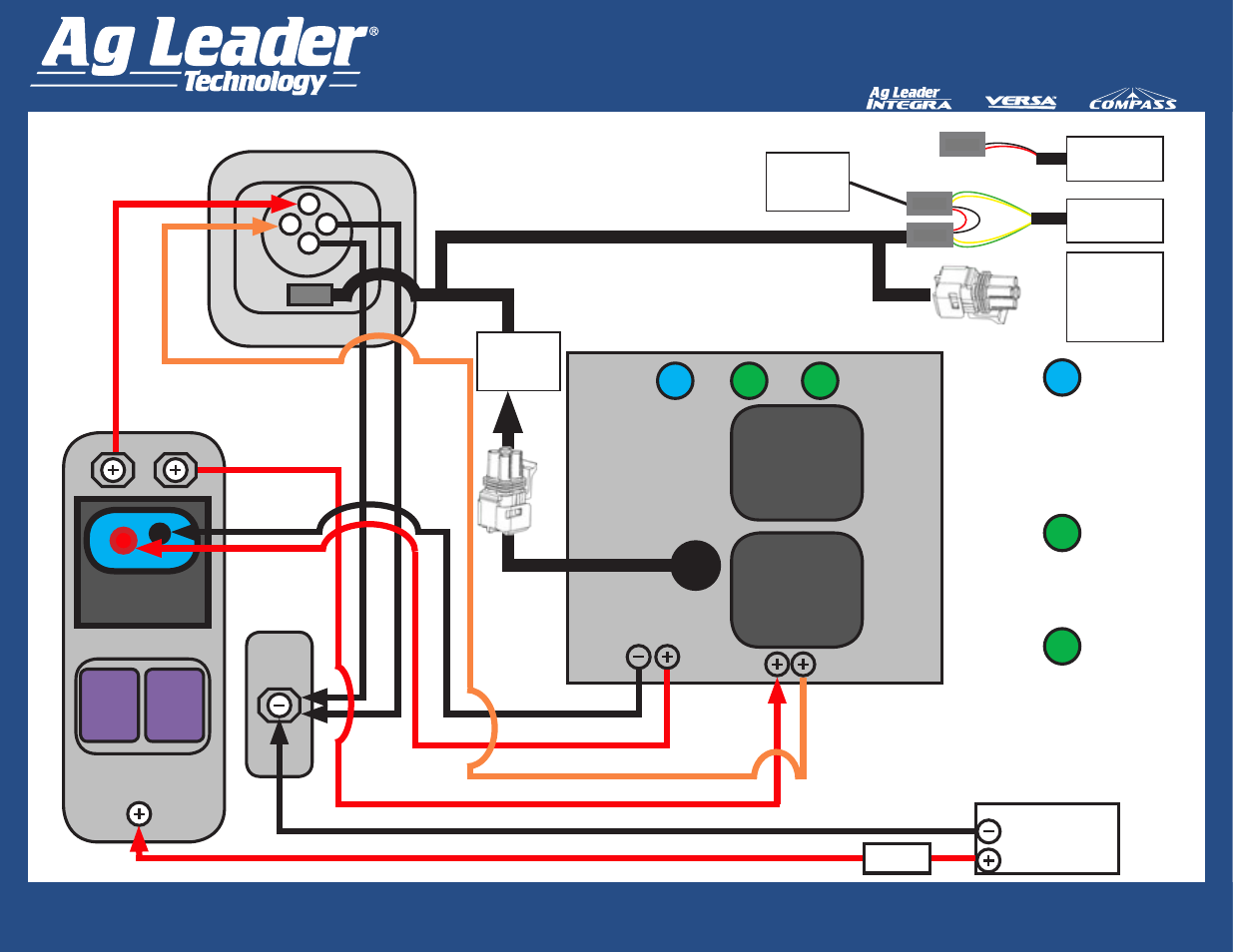
CAN
POWER
MODULE
Battery
100 amp
Fuse
Ground
60
amp
fuse
30
amp
fuse
High Current
Relay Module
CAN A
Relay
CAN B
Relay
LED
1
LED
2
LED
3
ISOBUS Battery Cable
PN 4002865-8,16,22
Pin#4=AWG10(30A) +12
ECU Power from Circuit Board
ISOBUS CAN Extension PN 4002586-8,16
Pin#3=A
WG8 (60A) from
Cooper Bussman Relay Module
Pin#2=A
WG10 (30A)
to Ground
Pin#1=A
WG8 (60A)
to Ground
Rear View of
ISO Plug
3
2
1
4
LED
1
Solid blue LED indicates module
is receiving +12V from the
display energizing the High
Current Relay controlling High
Current across pins 1 and 3 of
ISO plug.
LED
2
Solid green LED indicates CAN
A is receiving +12V from the
display when CAN A relay is
closed.
LED
3
Solid green LED indicates CAN
B is receiving +12V from the
module circuit board across pins
2 and 4 of ISO Plug when CAN
B relay is closed.
Weather
Pack Square
Shroud 4-pin
Power Control
Aux Power of
ISOBUS display
cable in cab
CAN B of
ISOBUS display
cable in cab
Weather Pack
Square Shroud
4-pin power
Control of
ISOBUS display
cable in cab
Aux
Power
ISO T
2-pin Metri-Pak
ISO T
Retrofit Cable Kit (Generic Tractor) Wiring Diagram
Active
Termination
Cable PN
4002587