Vt quick reference guide, Troubleshooting step 6: can power module led 2, Quick reference guide – Ag Leader Versa DirectCommand ISOBUS Quick Reference Guides User Manual
Page 13: Can power module, Start
13
VT Quick Reference Guide
Quick Reference Guide
AL: 2006300 - ENG Rev C
Is voltage
correct?
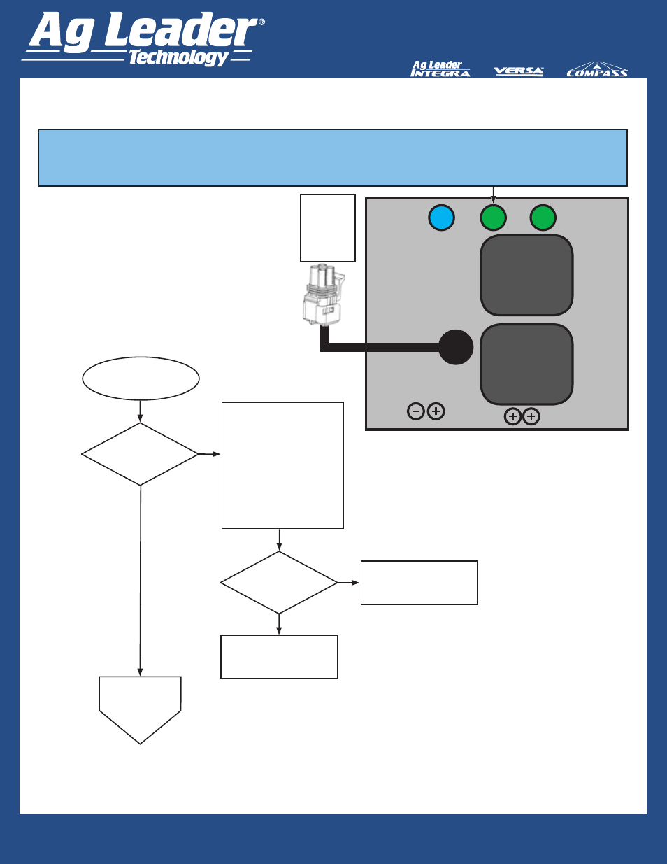
Troubleshooting Step 6: CAN Power Module LED 2
Start
Leaving the Power Control
Extension Cable plugged into
the CAN Power Module, back
Probe Pins B (Pink Wire)
and D (Black Wire) of Power
Control Extension Pigtail on
CAN Power Module for 12V
by removing seals on the
backside of 4 Pin Weatherpack
and inserting voltmeter probes
into Pins B and D.
LED Failed.
Contact Ag Leader
Dealer to Replace Module.
LED#2
Illuminated
GREEN?
Go to Step 7:
CAN Power
Module
LED 3
Yes
No
No
CAN A Relay Failed
Contact Ag Leader
Dealer to Replace Module.
Yes
4-pin Square
Weather
Pack with
Towers
Power
Control
CAN
POWER
MODULE
CAN A
Relay
CAN B
Relay
LED
1
LED
2
LED
3
LED #2 (Green) Indicates CAN A is being provided high current power (+12V) from the CAN A
Relay of the CAN Power Module.