Vt quick reference guide, Troubleshooting step 5: can power module led 1, Quick reference guide – Ag Leader Versa DirectCommand ISOBUS Quick Reference Guides User Manual
Page 12: Can power module, Start
12
VT Quick Reference Guide
Quick Reference Guide
AL: 2006300 - ENG Rev C
Correct
Voltages?
12V across A and D
5V across C and
D
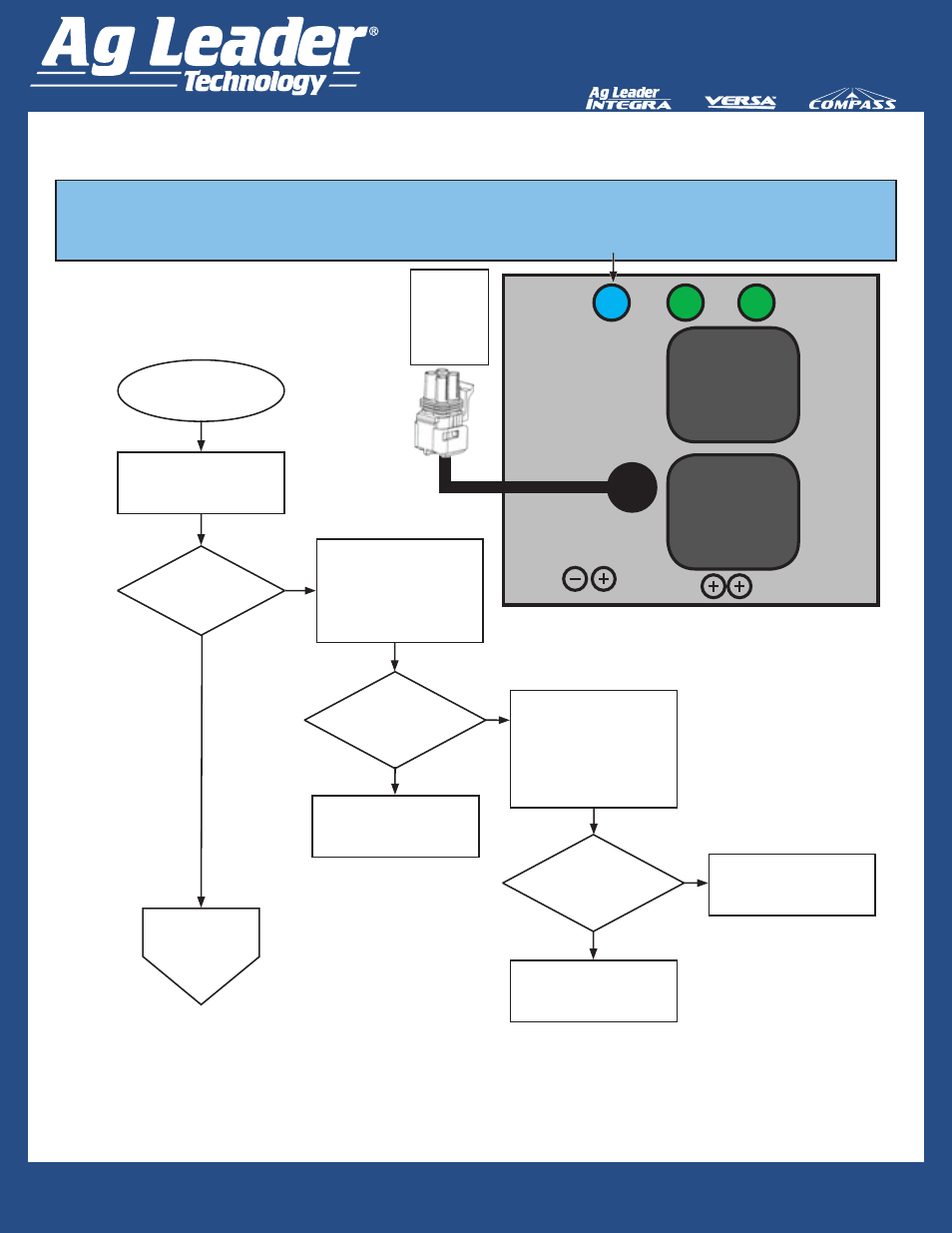
Troubleshooting Step 5: CAN Power Module LED 1
Start
Disconnect 4 Pin Power
Control Extension Cable from
module.
Check voltages across
Pins A and D
Pins C and D
of Extension Cable.
Contact Ag Leader Dealer for
Module Replacement.
Verify Display is Powered
On and
Tractor Key is On
Is
LED #1
Illuminated BLUE?
Go to Step 6
CAN Power
Module
LED 2
Yes
No
No
Disconnect 4 Pin Power
Control Extension Cable
From Display Cable In Cab.
Check voltages across
Pins A and D
Pins C and D
of Display Cable.
Replace Power Control
Extension
Cable.
No
Replace ISO Display Cable.
Yes
Yes
4-pin Square
Weather
Pack with
Towers
Power
Control
Correct
Voltages?
12V across A and D
5V across C and
D
CAN
POWER
MODULE
CAN A
Relay
CAN B
Relay
LED
1
LED
2
LED
3
LED #1 (Blue) Indicates that the module is receiving high current power (+12 VDC) from the
display energizing the High Current Relay Controlling High Current across Pins 1 and 3 of the ISO
plug.