SHIMPO DT-365E User Manual
Page 23
23
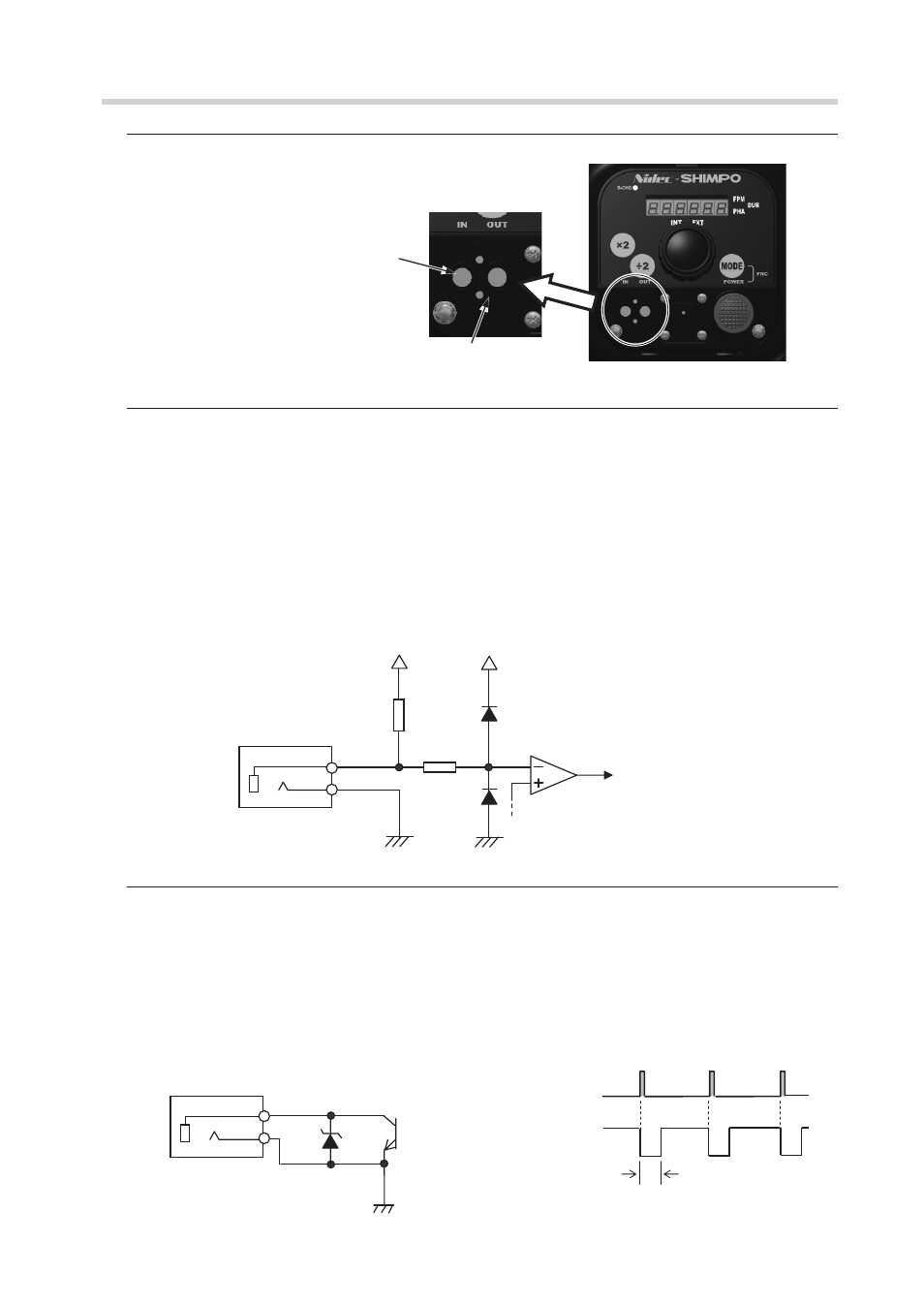
4.6 External I/O (phone jack)
4.6.1 Interface specifications
On the DT-365E main unit: Phone jack (φ3.5mm - 2 poles)
Use the φ3.5mm 2-pole phone plug for
connection cables for input/output signals.
4.6.2 External trigger pulse input
Connect the unit to external devices (sensors, etc.) to allow the strobe to emit light using the pulse
signal from the devices on external synchronous emission. (For details, refer to
"4.4 External
synchronous emission")
* Since there is a delay caused by the internal calculation process, the strobe emits light in
approximately 20 μs after the external trigger pulse is entered.
Available input frequency : Available measurement range 40 to 35,000 fpm
Available delay emission range 60 to 10,000 fpm
Available input signal
: NPN open collector signal
Available input pulse width : 50 μs or more
Available delay setting angle : within the range between 0 and 359º, available to set by 1º
Available delay setting time : within the range between 0 and 999 (max.) ms, available to set by 1 ms
Input signal
Jack
12V
Inside of DT-365E
Go to the input circuit
(insulated by photocoupler)
10kΩ
[Input circuit]
4.7k
12V
4.6.3 External trigger pulse output
Output the signal to external devices simultaneously with emission while emission is performed in
the internal oscillation mode or external trigger mode.
* Since there is a delay caused by the internal calculation process, the signal is output in
approximately 10 μs after emission.
Output circuit specifications : NPN open collector signal
Output pulse width
: Approx. 150 μs
Output signal
Jack
[Output circuit]
[Output timing]
Emission
NPN open collector output
Approx. 150 μs
Inside of DT-365E
(36V)
Input signal plug port
Output signal plug port