Electrical connections, 1 non ex versions – KROHNE UFM 530 HT EN User Manual
Page 22
4
ELECTRICAL CONNECTIONS
22
UFM 530 HT
www.krohne.com
12/2013 - 4002393201- HB UFM 530 HT R02 en
4.4 Electrical connections of the signal inputs and outputs
The signal inputs and outputs terminals are located in the converter terminal box. It is
accessible after removing the rear (blind) cover of the converter. There are versions for non Ex
and for Ex applications.
4.4.1 Non Ex versions
CAUTION!
For wiring of the signal inputs and outputs it is advised to use unshielded twisted pairs.
CAUTION!
Please observe instrument polarity: current (I) is always flowing towards I, C, P, A1, A2 terminals
(current sink).
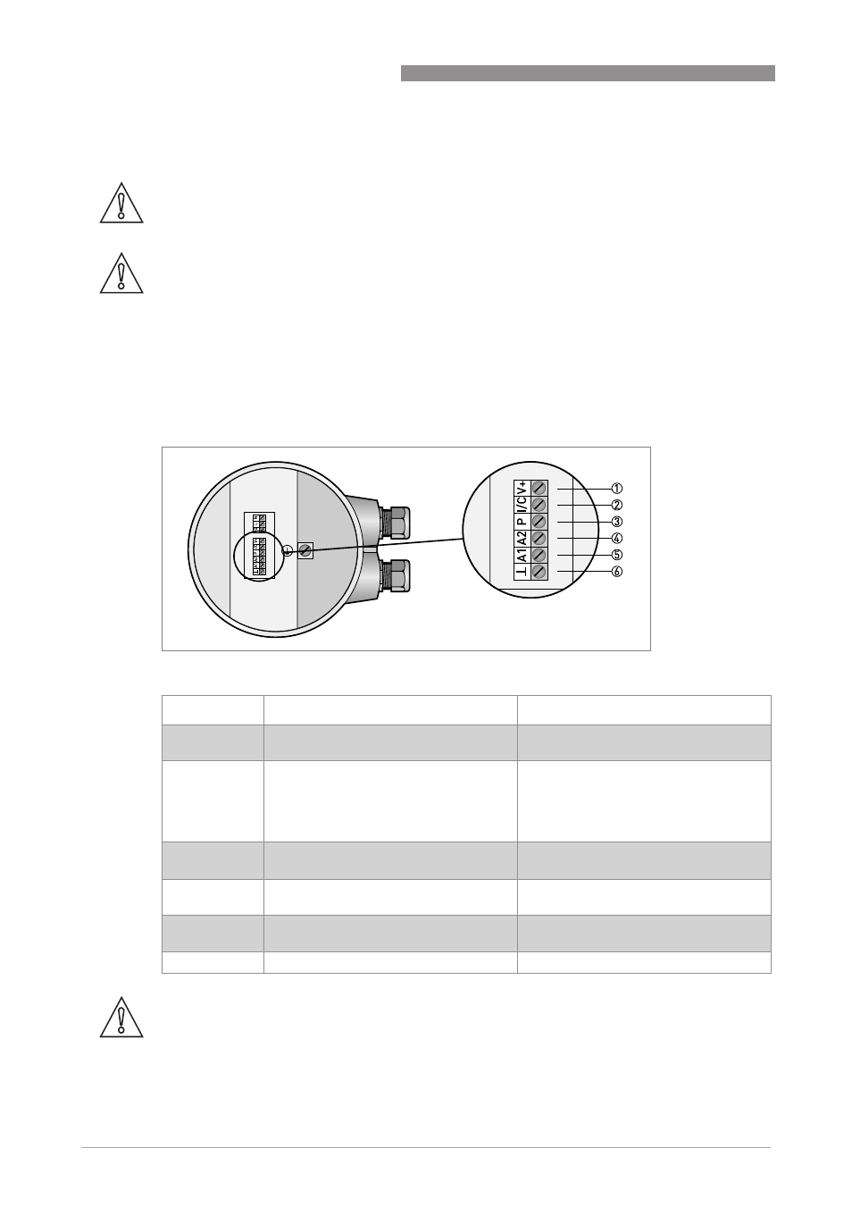
Non Ex standard version
Figure 4-4: Terminals for standard instrument.
Terminal
Function
Specification
1
DC power supply from converter for active
wiring of inputs and outputs.
22 VDC at full load, 24 VDC maximum,
I ≤ 100 mA.
2
Combined current output (I) and digital
input (C). Current output (I) includes
HART
®
-Communication.
Current output (I): I ≤ 22 mA,
R
load
≤ 680 Ω, U
max
= 15 VDC.
Digital input (C): low = 0...5 VDC,
high = 15...32 VDC (will be switched off
when current output activated).
3
Pulse / frequency output.
I
max
= 150 mA, U
max
= 32 VDC / 24 VAC,
maximal frequency = 2 kHz.
4
Analog input 2, for temperature or
pressure measurement.
0(4)...20 mA, R
i
= 58,2 Ω, fuse = 50 mA.
5
Analog input 1, for temperature
measurement.
0(4)...20 mA, R
i
= 58,2 Ω, fuse = 50 mA.
6
Common ground
-
CAUTION!
Never use the active and passive mode at the same terminal simultaneously.
If HART
®
-Communication is used, do not connect the pulse/frequency output P in active mode.