Table 2-9. internal jumper configuration, 9 status port, Status port -14 – KEPCO BHK-MG 40W (Half Rack) Series User Manual
Page 44: Internal jumper configuration -14, R.2.9, R. 2.9
2-14
BHK-1/2-MG SERIES 121313
2.9
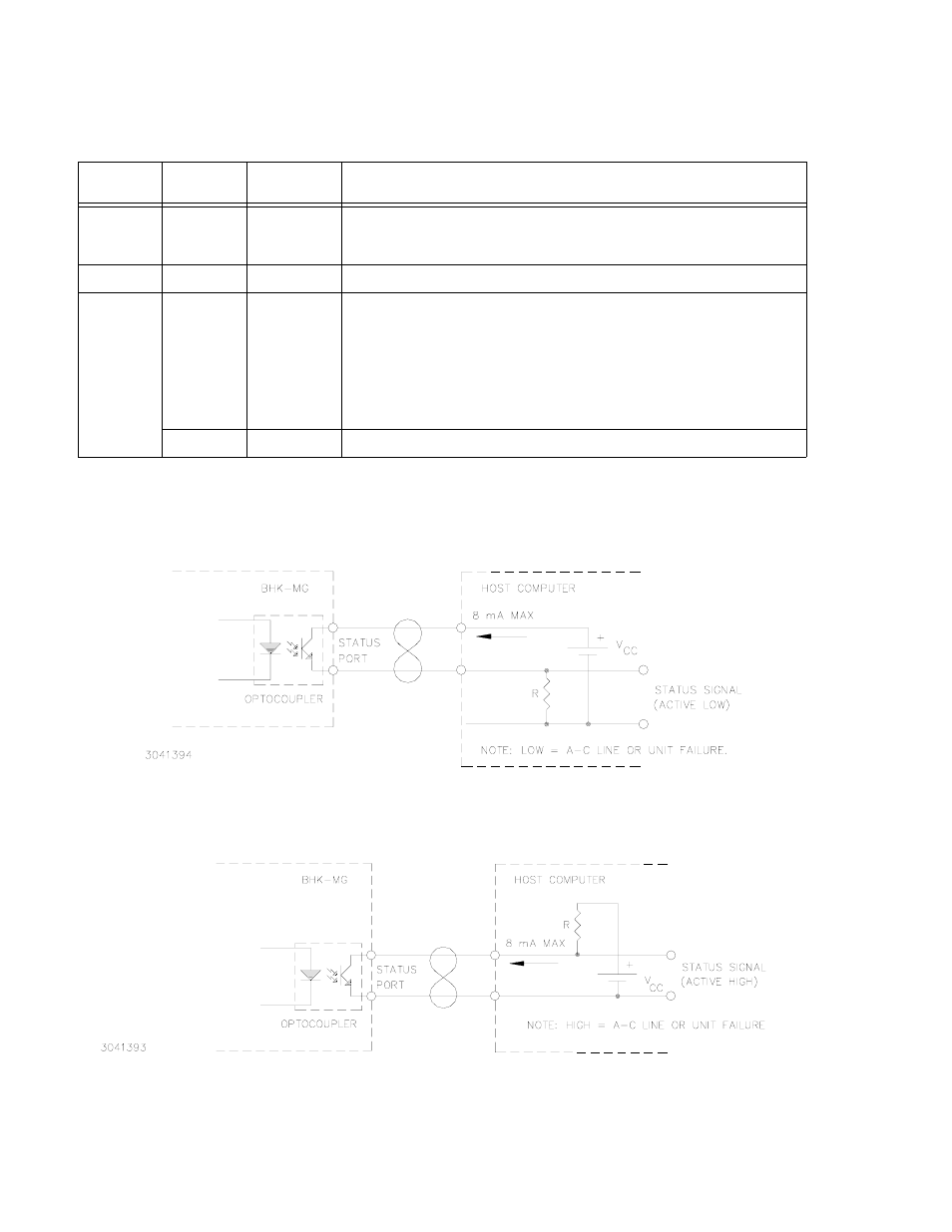
STATUS PORT
The status port opto-coupler can be configured for either active “low” (see Figure 2-6) or active
“high” (see Figure 2-7).
FIGURE 2-6. STATUS PORT OPTO-COUPLER ACTIVE “LOW” CONFIGURATION
FIGURE 2-7. STATUS PORT OPTO-COUPLER ACTIVE “HIGH” CONFIGURATION
TABLE 2-9. INTERNAL JUMPER CONFIGURATION
LOCATION
JUMPER
DEFAULT
STATUS
FUNCTION
A1
J6
Not Installed
For Service Personnel only. When installed (short circuit) a first time calibration
will be initiated. Use this jumper only when necessary, then remove the jumper
after calibration is initiated.
A2
JP1
Installed
Enables input circuit breaker to trip when arcing at the output is detected.
A3
JP1
Installed
between pin
1 and 2
Jumper installed between pins 1 and 2: Prepares unit to receive a Relay N. (nor-
mally) Open Contact between pins 1 and 2 of the Status and Remote On/Off Port.
When contact is open unit is turned ON; when contact is closed, unit is turned
OFF.
Jumper installed between pins 2 and 3: Prepares unit to receive a Relay N. (nor-
mally) Closed Contact between pins 1 and 3 of the Status and Remote On/Off
Port. When contact is closed unit is turned ON; when contact is open, unit is
turned OFF.
JP2
Installed
Enables input circuit breaker to trip when input power loss is detected.