Table 2-2. ieee 488 port connector pin assignments, Ieee 488 port connector pin assignments -4, Able 2-2 fo – KEPCO BHK-MG 40W (Half Rack) Series User Manual
Page 34: Able 2-3
2-4
BHK-1/2-MG SERIES 121313
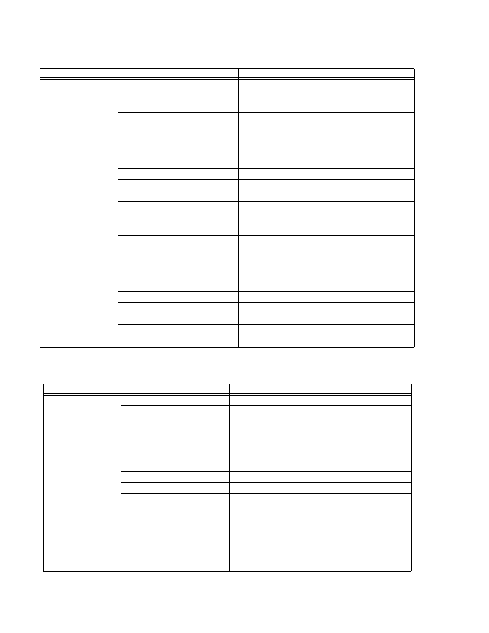
TABLE 2-2. IEEE 488 PORT CONNECTOR PIN ASSIGNMENTS
CONNECTOR
PIN
SIGNAL NAME
FUNCTION
IEEE 488
PORT
A1J1
1
D
I
01
I/O Line
2
D
I
02
I/O Line
3
D
I
03
I/O Line
4
D
I
04
I/O Line
5
EOI
End or Identify
6
DAV
Data Valid
7
NRFD
Not Ready for Data
8
NDAC
Not Data Accepted
9
IFC
Interface Clear
10
SRQ
Service Request
11
ATN
Attention
12
SHIELD
Shield
13
D
I
05
I/O Line
14
D
I
06
I/O Line
15
D
I
07
I/O Line
16
D
I
08
I/O Line
17
REN
Remote Enable
18
GND
Ground (signal common)
19
GND
Ground (signal common)
20
GND
Ground (signal common)
21
GND
Ground (signal common)
22
GND
Ground (signal common)
23
GND
Ground (signal common)
24
LOGIC GND
Logic Ground
TABLE 2-3. STATUS AND REMOTE ON/OFF PORT CONNECTOR PIN ASSIGNMENTS
CONNECTOR
PIN
SIGNAL NAME
FUNCTION
STATUS AND
REMOTE ON/OFF
PORT
CONNECTOR A3J14
1
Armature
Relay control armature contact.
2
N-open
Normally open relay control input: pins 1 - 2 open for output
ON, pins 1 - 2 closed for output OFF (Jumper A3JP1 should
be in the factory default position, between pins 1 and 2).
3
N-closed
Normally closed relay control input: pins 1 - 3 closed for out-
put ON, pins 1 - 3 open for output OFF (Jumper A3JP1
should be inserted between pins 2 and 3).
4
5V Return
Return for TTL control
5
Not Used.
6
TTL
TTL control input: Logic 0 for unit ON, logic 1 for unit OFF.
7
Collector
Collector of LED-transistor optocoupler. Notifies host com-
puter of absence of a-c input or a major power supply failure,
active “high” (see PAR 1.4.9), requires pin 8 to be connected
to the “–“ of the host computer d-c supply as described in
PAR.2.9.
8
Emitter
Emitter of LED-transistor optocoupler. Notifies host computer
of absence of a-c input or a major power supply failure, active
“low” (see PAR 1.4.9), requires pin 7 to be connected to the
“+“ of the host computer d-c supply as described in PAR. 2.9.