4 positive output, negative terminal grounded, 5 negative output, positive terminal grounded, 8 operating configuration – KEPCO BHK-MG 40W (Half Rack) Series User Manual
Page 43: Positive output, negative terminal grounded -13, Negative output, positive terminal grounded -13, Operating configuration -13
BHK-1/2-MG SERIES 121313
2-13
between terminals TB1-5 (GND NET) and TB1-6 (+S). To disconnect the grounding network
from the output, remove the connection across TB1-5 and TB1-6 (see Figure 2-4).
2.7.5.4
POSITIVE OUTPUT, NEGATIVE TERMINAL GROUNDED
To configure the BHK-MG as a positive output power supply (referenced to ground), connect the
negative output terminal to ground: connect TB1-4 (GND - CHASSIS) to TB1-3 (–S). To avoid
degraded load regulation in current mode it is necessary to remove the grounding network from
the circuit by removing the link between TB1-6 (+S) and TB1-5 (GND NET).
2.7.5.5
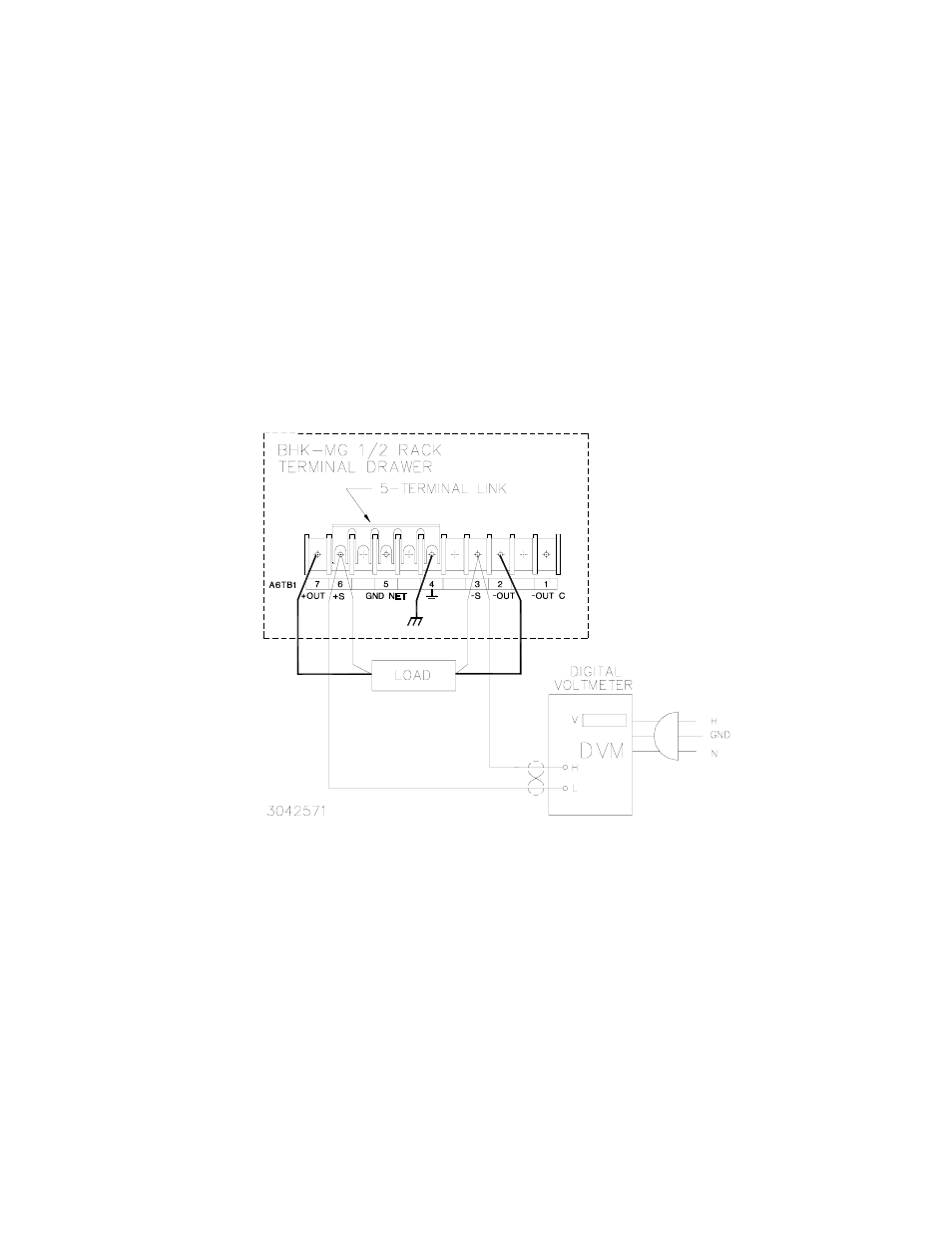
NEGATIVE OUTPUT, POSITIVE TERMINAL GROUNDED
To configure the BHK-MG as a negative output power supply (referenced to ground), connect
the positive output terminal to ground: use a 5-terminal link to connect TB1-4 (GND - CHASSIS)
to TB1-6 (+S). Note that when the positive output is grounded, the ground network (TB1-5) is
inoperative (see Figure 2-5).
FIGURE 2-5. REMOTE SENSING, FAST MODE SELECTED, POSITIVE OUTPUT GROUNDED
2.8
OPERATING CONFIGURATION
The complete operating configuration is defined by jumper configuration of internal boards.
Table 2-9 lists the location of the internal jumpers and their function. This information is provided
for reference purposes only, to indicate the configuration options available. Do not attempt to
alter the jumper configuration. For assistance in changing any jumper-selected parameter con-
tact Kepco Applications Engineering.