1 local sensing/remote sensing select, 2 fast mode/slow mode select, 3 grounding network configuration – KEPCO BHK-MG 40W (Half Rack) Series User Manual
Page 42: Local sensing/remote sensing select -12, Fast mode/slow mode select -12, Grounding network configuration -12, Re 2-4, Figures 2-4 and 2
2-12
BHK-1/2-MG SERIES 121313
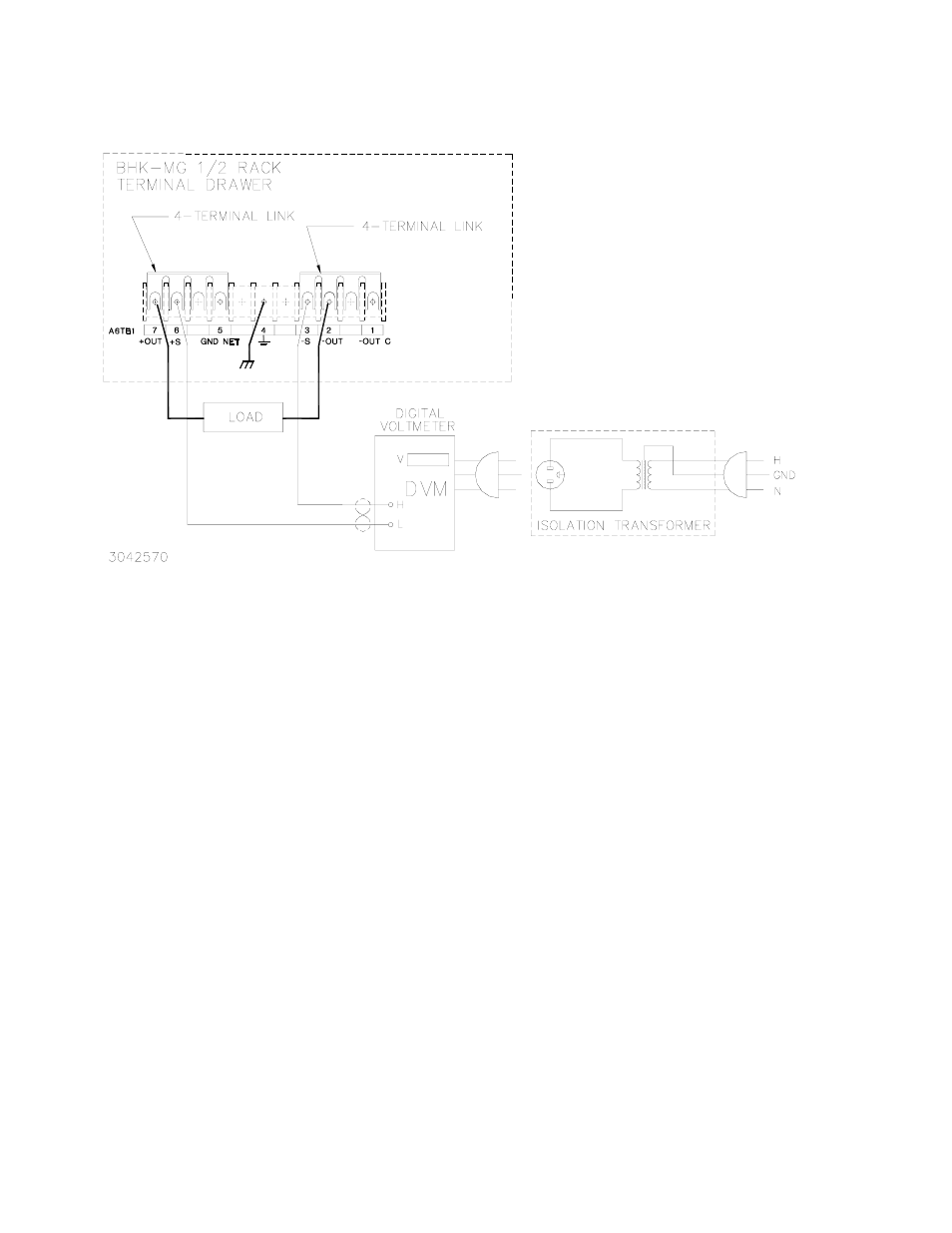
FIGURE 2-4. LOCAL SENSING, SLOW MODE SELECTED, GROUNDING NETWORK CONNECTED,
FLOATING OUTPUT (FACTORY DEFAULT CONFIGURATION)
2.7.5.1
LOCAL SENSING/REMOTE SENSING SELECT
Local sensing (factory default configuration) is established by connecting terminals TB1-6
(+S) to TB1-7 (+OUT) and TB1-2 (–OUT) to TB1-3 (–S) (see Figure 2-4). The power supply is
shipped with these connections installed for local sensing.
Remote sensing is established by removing the links between TB1-6, TB1-7 and TB1-2, TB1-3.
The +S and –S lines must be connected at the load (see Figure 2-5).
2.7.5.2
FAST MODE/SLOW MODE SELECT
Fast mode is established when there is no connection between TB1-2 (–OUT) and TB1-1 (–
OUT C) (see Figure 2-5). Slow mode (factory default configuration) can be established by con-
necting TB1-2 to TB1-1, thus connecting the internal output capacitor to the output (see Figure
2-4).
2.7.5.3
GROUNDING NETWORK CONFIGURATION
When the output is floating there is a tendency for large changes in output voltage to affect the
digital programming section, possibly resulting in an erroneous output. The parallel RC ground-
ing network is designed to be connected to ground at the output when the output is floating to
ensure that the digital programming section is not adversely affected by the dynamic swing of
the output. The power supply is shipped with the grounding network connected: a connection