Operation – INOR IPAQ R520X User Manual
Page 30
5
OPERATION
C520/C520X / R520/R520X
09/2010 • 86B5200001
www.inor.com
30
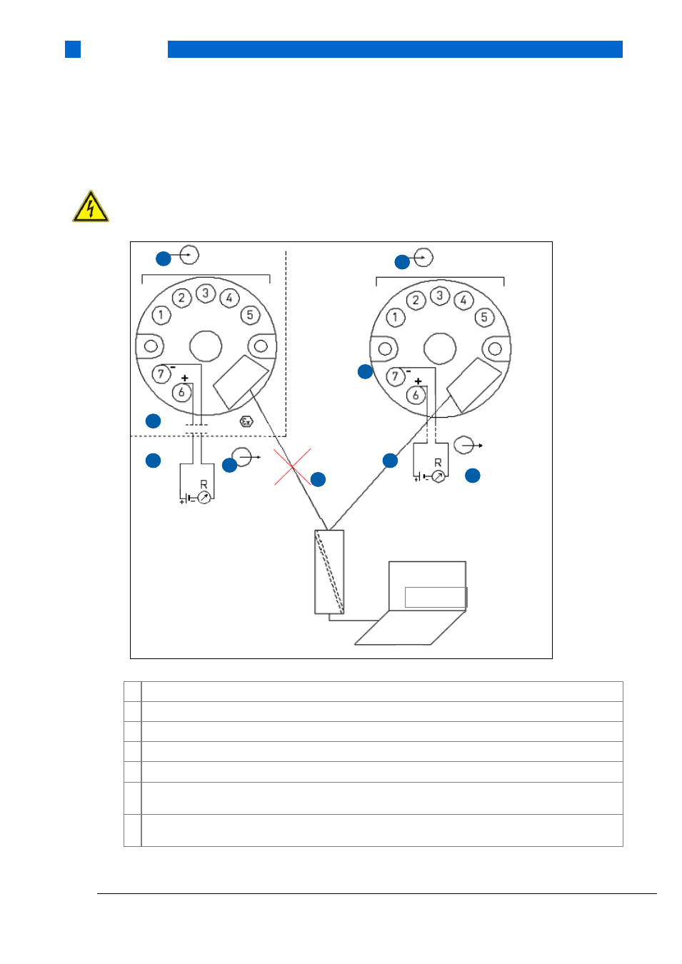
Proper connection of the transmitters with a PC requires an INOR USB Interface (see Figure 17
for connection of the C520/C520X transmitters and figure 18 for connection of the R520/R520X
transmitters).
ATTENTION!
Make sure the area is safe before connecting the INOR USB Interface ICON to the transmitter.
Figure 17: Connection during configuration of C520/C520X
1 Input (intrinsically safe)
2 Output voltage supply (intrinsically safe terminals 6 and 7) and R
Load
(intrinsically safe)
3 Communication with USB Interface and PC software ConSoft
4 Safe area
5 Classified hazardous area (potentially explosive area e.g. Zone 0, 1 or 2)
6 Connection to USB Interface and PC software ConSoft is not permitted if C520X is placed in the
classified hazardous area (potentially explosive area)
7 Connection to the voltage supply during configuration with USB Interface and PC software ConSoft is
not needed
ConSoft
1
2
3
1
2
6
5
4
4