Electrical connections – INOR IPAQ R520X User Manual
Page 14
4
ELECTRICAL CONNECTIONS
C520/C520X / R520/R520X
09/2010 • 86B5200001
www.inor.com
14
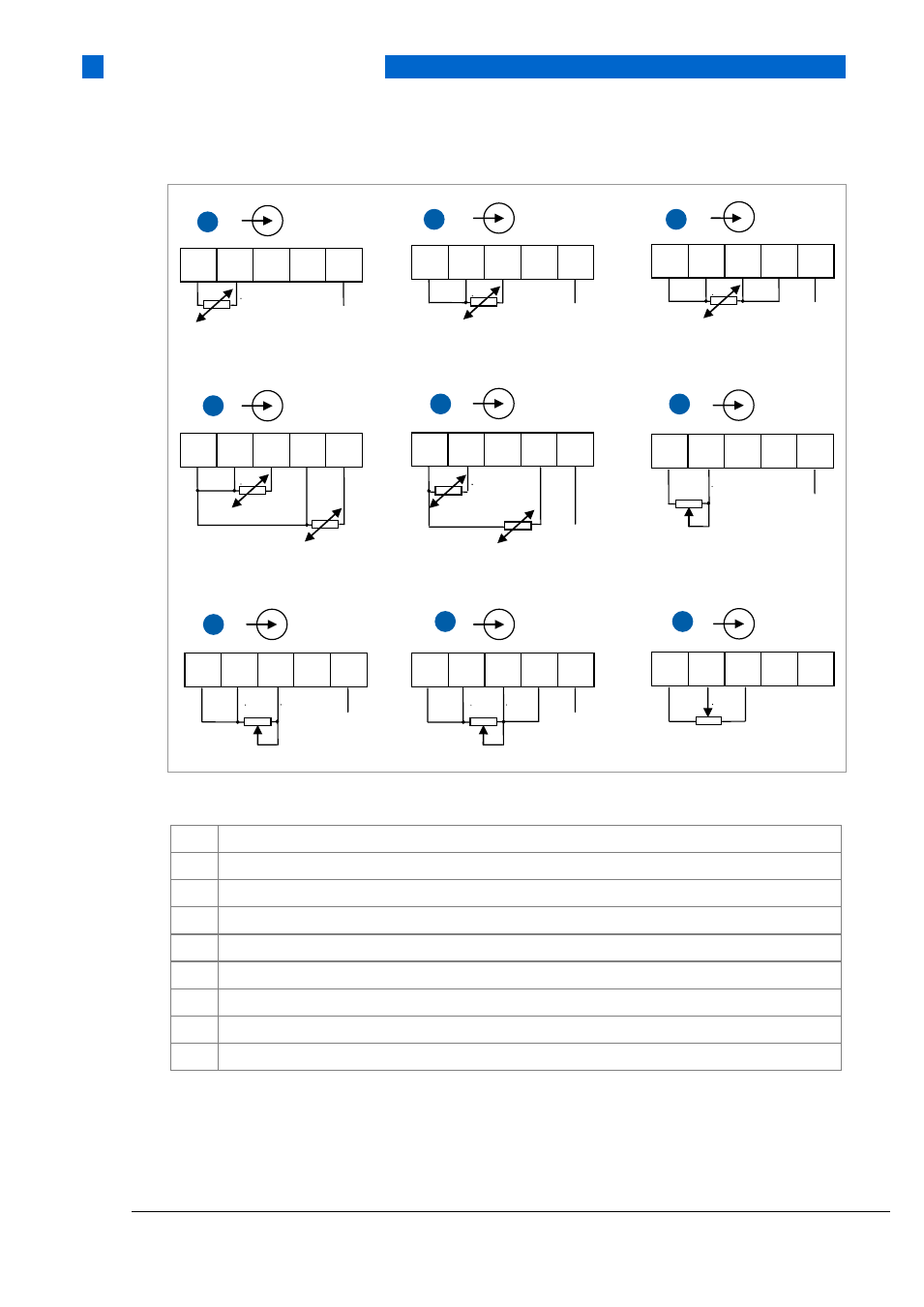
Figure 5: Installation diagram, RTD resistance and potentiometer measurement C520/C520X
1
Pt100…Pt1000, Ni100, Ni120, Cu10 2-wire connection
2
Pt100…Pt1000, Ni100, Ni120, Cu10 3-wire connection
3
Pt100…Pt1000, Ni100, Ni120, Cu10 4-wire connection
4
RTD, redundant sensor elements 2 x 3-wire connection
5
RTD, redundant sensor elements 2 x 2-wire connection
6
Resistance, 2-wire connection
7
Resistance, 3-wire connection
8
Resistance, 4-wire connection
9
Potentiometer, 3-wire connection
1) SmartSense wire
1
2
3
4
5
1)
7
0%
100%
1
2
3
4
5
1)
1
1
2
3
4
5
1)
2
1
2
3
4
5
1)
3
1
2
3
4
5
4
1
2
3
4
5
1)
5
1
2
3
4
5
1)
6
0%
100%
1
2
3
4
5
9
0%
100%
1
2
3
4
5
1)
8
0%
100 %