Electrical connections – INOR IPAQ R520X User Manual
Page 19
4
ELECTRICAL CONNECTIONS
C520/C520X / R520/R520X
09/2010 • 86B5200001
www.inor.com
19
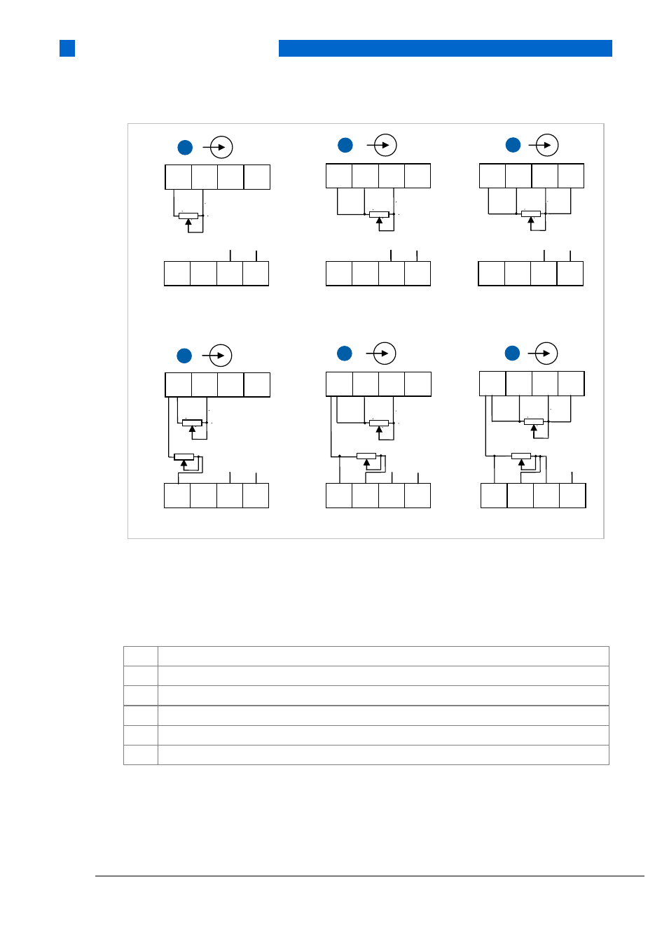
Figure 10: Installation diagram, resistance connections for R520/R520X
1) SmartSense wire
2)
GND (input cable screen)
1
Resistance, 2-wire connection Ch 1
2
Resistance, 3-wire connection Ch 1
3
Resistance, 4-wire connection Ch 1
4
Dual resistance, 2-wire connection on Ch 1 and Ch2
5
Dual resistance, 3-wire connection on Ch 1 and Ch2
6
Dual resistance, 4-wire connection on Ch 1 and Ch2
3
5
6
7
8
Ch 2
1
2
3
4
Ch 1
0%
100%
2)
1)
2
5
6
7
8
Ch 2
1
2
3
4
Ch 1
0%
100%
2)
1)
1
5
6
7
8
Ch 2
1
2
3
4
Ch 1
0%
100%
2)
1)
1
2
3
4
Ch 1
5
6
7
8
Ch 2
4
0%
100%
0%
100%
2)
1)
1
2
3
4
Ch 1
5
6
7
8
Ch 2
5
0%
100%
0% 100%
2)
1)
1
2
3
4
Ch 1
5
6
7
8
6
0%
100%
0%
100%
Ch 2
2)