2 configuration of the c520/c520n/c520, X / r520/r520n/r520x, Operation – INOR IPAQ R520X User Manual
Page 26
5
OPERATION
C520/C520X / R520/R520X
09/2010 • 86B5200001
www.inor.com
26
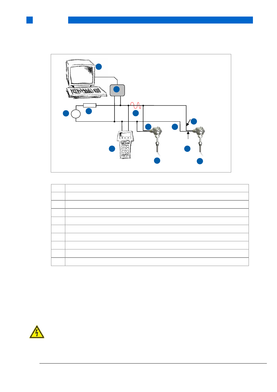
Figure 16: C520 in a multipoint connection (multi-drop mode) with up to 64 devices in parallel
1
Primary master
2
HART modem
3
Secondary master
4
Load
≥ 250 Ω
5
DC power supply
6
Terminal 6
7
Terminal 7
8
C520 or R520 loop current mode disabled up to 64 slaves can be connected
9
4 mA
10
HART
Figure 16 shows a multipoint connection (multi-drop) with up to 64 devices (C520/R520 or other
HART equipment) in parallel. The device's current outputs must be passive.
Burst mode is not supported.
5.2 Configuration of the C520/C520N/C520X / R520/R520N/R520X
ATTENTION!
Only an Ex approved HART modem located in safe area may be connected to a transmitter
placed in potentially explosive area.
In the table below are the factory settings of the C520/C520X / R520/R520X transmitters.
+
2
1
3
8
4
5
6
7
9
9
10
8