5 r520/r520n/r520x connections – INOR IPAQ R520X User Manual
Page 18
4
ELECTRICAL CONNECTIONS
C520/C520X / R520/R520X
09/2010 • 86B5200001
www.inor.com
18
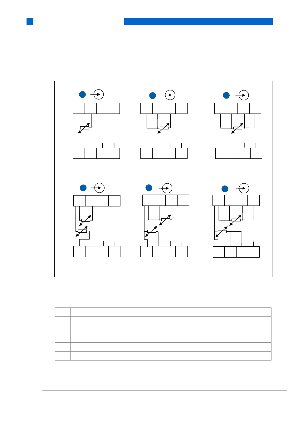
4.5 R520/R520N/R520X connections
Figure 9: Installation diagram, RTD connections for R520/R520X
1) SmartSense wire
2) GND (input cable screen)
1
Pt100…Pt1000, Ni100, Ni120, Cu10 2-wire connection Ch 1
2
Pt100…Pt1000, Ni100, Ni120, Cu10 3-wire connection Ch 1
3
Pt100…Pt1000, Ni100, Ni120, Cu10 4-wire connection Ch 1
4
RTD, redundant sensor elements 2 x 3-wire connection Ch 1+ Ch 2
5
RTD, redundant sensor elements 2 x 2-wire connection Ch 1+ Ch 2
6
RTD, redundant sensor elements 2 x 4-wire connection Ch 1+ Ch 2
2
1
2
3
4
Ch 1
5
6
7
8
Ch 2
3
1
2
3
4
Ch 1
5
6
7
8
Ch 2
2)
1)
2)
1)
1
1
2
3
4
Ch 1
5
6
7
8
Ch 2
2)
1)
4
1
2
3
4
Ch 1
5
6
7
8
Ch 2
2)
1)
6
1
2
3
4
Ch 1
5
6
7
8
Ch 2
2)
5
Ch 1
1
2
3
4
5
6
7
8
Ch 2
2)
1)