3 installation, 1 installation of the c520/c520n/c520x, Installation – INOR IPAQ R520X User Manual
Page 10: 1 installation of the c520/c520n/c520
3
INSTALLATION
C520/C520X / R520/R520X
09/2010 • 86B5200001
www.inor.com
10
3
Installation
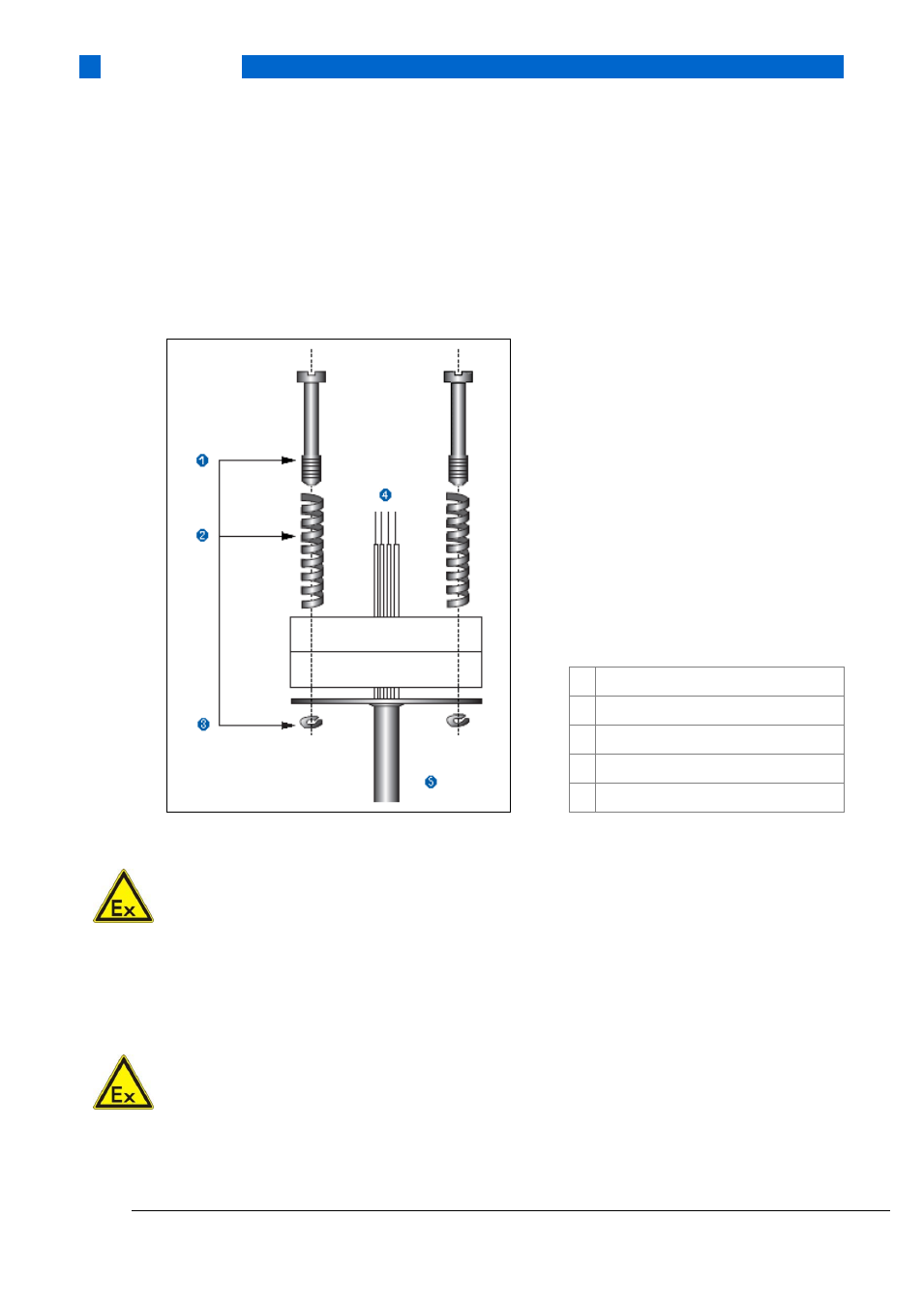
3.1 Installation of the C520/C520N/C520X
The C520/C520X is intended for installation in DIN B connection heads or larger. The large
Ø7 mm / 0.28” center hole (see Chapter 6.1.3) facilitates the electrical connection of the
measurement sensor and the installation.
Figure 3: Connection head installation kit 70ADA00017
ATTENTION!
The C520 transmitter may not be installed in potentially explosive areas other than Zone 2 and
Division 2. For Zone 2/Div 2 applications a Class 2 power supply placed in safe area is needed.
In other potentially explosive areas, the C520X must be used.
The transmitter C520X must be supplied by an intrinsically safe power supply unit or Zener
barrier placed outside of the potentially explosive zone.
ATTENTION!
The C520X transmitter must be installed in a housing with the protection rating IP20 or better
according to EN 60529 / IEC 60529.
For Zone 2 applications the C520 must be mounted in an enclosure with at least IP54 according
to EN 60529 / IEC 60529.
1 Screw, M4
2 Spring
3 Lock washer
4 Pt100
5 Protective tube