6 connection diagram, r520, Electrical connections – INOR IPAQ R520X User Manual
Page 22
4
ELECTRICAL CONNECTIONS
C520/C520X / R520/R520X
09/2010 • 86B5200001
www.inor.com
22
R
≥250 Ω
1
2
4
4
3
5
Test
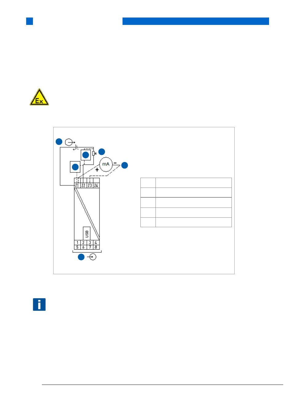
4.6 Connection diagram, R520
ATTENTION!
IPAQ R520 is a Category 3 equipment and may only be installed in an area with a potentially
explosive atmosphere Zone 2 / Division 2 or it may be installed in safe area and connected to a
sensor located in an area with a potentially explosive atmosphere Zone 2 / Division 2!
1
Voltage supply 10…36 VDC
2
R
Load
, R
≥250 Ω
3
Input
4
Modem
5
Test connection (R
i
≤10 Ω)
Figure 13: R520 connection diagram
NOTE!
The HART modem is connected parallel to the output load or parallel to the output of the
transmitter (see Figure 13).
This manual is related to the following products: